|
#4330101 - 01/21/17 12:17 AM
 Re: F16-FLCS + TQS (Original) USB Conversion
[Re: Viper1970]
Re: F16-FLCS + TQS (Original) USB Conversion
[Re: Viper1970]
|
Joined: Dec 2016
Posts: 454
Kb1rd1

Member
|
Member
Joined: Dec 2016
Posts: 454
|
I think you have to seperate the two buttons using diodes, so that the circuit is independent, cause you press two buttons together if you use this originally two stage trigger. If the first button is pressed, the second will be ignored as long as the first still remains pressed.
Simply test it if they work without the mechanic and each one seperate. If so, you could use diodes. Okay , good thought , but they go back through the Shift Register board in the Original FLCS Handle , so I dont think I can add a Diode ,but perhaps they could be rewired if needed with new wires ?, but it maybe more trouble than it is worth really , perhaps I will just have Guns on the trigger and put Missles on other Button instead eg S1 or S2. KB
|
|
#4330117 - 01/21/17 02:22 AM
 Re: F16-FLCS + TQS (Original) USB Conversion
[Re: Viper1970]
Re: F16-FLCS + TQS (Original) USB Conversion
[Re: Viper1970]
|
Joined: Nov 2001
Posts: 3,955
Sokol1
Senior Member
|
Senior Member
Joined: Nov 2001
Posts: 3,955
Internet
|
Don't know how Thrustmaster originally made the logic for the grip pcb (shift register). Maybe they have used a seperate methode for the two stage trigger, cause you could also change them between simple joystick button and keyboard emulation.
No, "two stage trigger" don't use "special hardware", is just 2 individual micro swtich pressed be same lever (trigger), they are seen by Shift Register PCB (ande joystick firmware) as 2 separated buttons. The 2 micro switchs (yellow) inside TM F22PRO grip (same arrange for Cougar, TMW).  http://i67.tinypic.com/6r283o.jpg http://i67.tinypic.com/6r283o.jpgBTW - In the picture above the screw over lower switch is user "mod", to make the trigger less "heavy", more suitable for WWII planes.
Don't know how Mjoy uses the Thrustmaster shift register. Never have made anything with Mjoy.
MMjoy2 handle Shift Register boards in the same way that Tm controllers, buttons press, protocol serial signal for the controller.
|
|
|
#4330127 - 01/21/17 03:17 AM
Re: F16-FLCS + TQS (Original) USB Conversion
[Re: Viper1970]
|
Joined: Dec 2016
Posts: 454
Kb1rd1
Member
|
Member
Joined: Dec 2016
Posts: 454
|
Already gone to bed and while thinking of your problem, something came to my mind.
The two stage trigger always acts like two simultaneously pressed buttons. In real fighter jets you have the gun cam on one stage also. Or you could use it for a laser designator on stage one before you fire your weapon with stage two etc.
That's why they are always pressed together if you are at stage two. Only the first stage TG1 is stand alone. If you press completely down, TG1 and TG2 are both activated. That's the reason for this mechanic.
And for the missles it also more realistic to use a seperate button (I use S2 for example), the trigger is for the guns only in most of the fighter jets (not all, but most).
Yes I was thinking I would use S2 as the Missle Button too, Sokol's Pics are what I have , except In the 1st pic I don't see a PCB with S.Reg. , it appears the Handle was totally rewired....I don't have the F22 so maybe that was how it is. I think I saw a Trigger Mod somewhere during all this googling , perhaps at Cougar World? I will need to look further into it. CW Trigger Fix ** there is one at Cougar World but not the one I was thinking of , which looked similar to Sokol's 2nd Pic (linked above) KB
Last edited by Kbird; 01/21/17 03:18 AM.
|
|
|
#4330155 - 01/21/17 12:08 PM
Re: F16-FLCS + TQS (Original) USB Conversion
[Re: Kb1rd1]
|
Joined: Nov 2001
Posts: 3,955
Sokol1
Senior Member
|
Senior Member
Joined: Nov 2001
Posts: 3,955
Internet
|
Yes I was thinking I would use S2 as the Missle Button too, Sokol's Pics are what I have , except In the 1st pic I don't see a PCB with S.Reg. , it appears the Handle was totally rewired....
Yep, that grip was rewired using diode matrix instead the Shift Register.  BTW - This mod you link is just a "feel" mod - add a extra spring for weight - don't change electronics.
|
|
|
#4330359 - 01/22/17 09:33 AM
Re: F16-FLCS + TQS (Original) USB Conversion
[Re: Kb1rd1]
|
Joined: Apr 2002
Posts: 160
undefined
Member
|
Member
Joined: Apr 2002
Posts: 160
|
.
Last edited by jamiroq; 07/21/18 03:05 PM.
|
|
|
#4330494 - 01/22/17 08:21 PM
Re: F16-FLCS + TQS (Original) USB Conversion
[Re: Kb1rd1]
|
Joined: Dec 2010
Posts: 1,179
Viper1970
Member
|
Member

Joined: Dec 2010
Posts: 1,179
Bavaria, near Munich
|
Hello Kbird,
I have the F22, but haven't opened its grip until now. I think it has the same shift register as the FLCS. Only thing I've seen, is that the main pcb in the base are different between the F22 and the FLCS. The FLCS has the one which looks like a set square, while the one of the F22 is more like the one which is used in the Cougar (shaped like a simple square).
The picture Sokol showed, is the same principle as my grips are wired, except the go to the original Thrustmaster base pcb thru a 25pin parallel connector instead of a Plasma board, which sits in my cockpit and not in the sticks base anymore. I go this way to make my grips in the pit interchangeable. First I wanted to use a shift register for each handle, but due to some pros for my hardware setting and some other reasons ( only have a limited number of shift registers, but want to be able to built more handles in future) I decided to do it this way. Only drawback is the huge number of cables you have to solder to the connectors.
CockpitPC1: Ryzen9 5950X|64GB DDR4|512GB M2 SSD|2TB M2 SSD|Geforce RTX3090|Reverb G2|Win11Pro
CockpitPC2: PhenomII X6 1100T|32GB DDR2|2x 2TB HDD|2x Geforce GTX660 SLI|Win7Pro64
ComUnitPC1: Ryzen9 3900XT|32GB DDR4|2x 2TB HDD|Geforce RTX2070|Win11 Pro
ComUnitPC2: PhenomII X6 1100T|16GB DDR2|2x 2TB HDD|Geforce GTX660|Win7Pro64
ComUnitPC3: AthlonII X2 250|2GB DDR2|2TB HDD|Geforce 5950Ultra|2x VoodooII SLI|WinXPPro32&WinME
ComUnitPC4: K6-2+|768MB SDR|640GB HDD|Geforce 256DDR|VoodooI|Win98SE
|
|
|
#4330537 - 01/23/17 01:41 AM
Re: F16-FLCS + TQS (Original) USB Conversion
[Re: Sokol1]
|
Joined: Dec 2016
Posts: 454
Kb1rd1
Member
|
Member
Joined: Dec 2016
Posts: 454
|
Yes I was thinking I would use S2 as the Missle Button too, Sokol's Pics are what I have , except In the 1st pic I don't see a PCB with S.Reg. , it appears the Handle was totally rewired....
Yep, that grip was rewired using diode matrix instead the Shift Register. BTW - This mod you link is just a "feel" mod - add a extra spring for weight - don't change electronics. thx, Yes you are right, I could not find the Mod of the F22 Trigger that someone changed with a leaf Spring,epoxy putty and a small screw again.... I'll post back here if I do... KB
|
|
|
#4330548 - 01/23/17 02:44 AM
Re: F16-FLCS + TQS (Original) USB Conversion
[Re: Viper1970]
|
Joined: Dec 2016
Posts: 454
Kb1rd1
Member
|
Member
Joined: Dec 2016
Posts: 454
|
Found the schematic on my HD, have used it for my pit project too, cause I also had this column and row understanding problem  : (It's simple and clear to understand)  I thought I had seen that Image before , and I had saved it but forgot about it, but the one I have (below) makes me now think even though my TQS Buttons are now (mostly) all working in MMjoy2 that the diodes are the wrong way around. In the image below, the diodes are on the Row wires with the stripes towards the wires (Arduino Board) not the switch....or is that the same as having them on the Column wires with the stripe towards the switch ? (which is what I have I believe)  Button Matrixes Button Matrixes are making me think I have a couple of diodes on my Cranial Implant facing the wrong way too stuff ain't getting in It didn't help that I didn't notice that there is (was) a small bare wire soldered between the two posts on the ANT Knob on the PWR side of the Pot so nothing was working at 1st as I had shorted the switches when adding the Pot's +5v wire, when I attached the Green Wire from the old Eraser Nub as my Pot PWR as SolderMonkey had instructed earlier. (Blue Wire in Ribbon is Pot GND/COM) Once I cut that link and put the ANT switch (T6) on it's own wire to the Arduino, things started to work as I expected. I can't however work out/understand how MMJoy2 is setup to Input the Button Matrix fully, I never used MMjoy or MegaMozg's earlier Firmwares, perhaps I should google those tutorials? That section of MMJoy2 only shows (2) 10 input lines even though it supports 132 buttons. I had thought perhaps you program one Row at a time and send it to the Leonardo but that didn't work. I have more buttons than I can put on one Row , so far I have B3 Row (+8 switches) and the ANT switch at B1 Row Setup but I still have the X-Fighter Hat switch I installed to replace the Eraser Nub to setup on B2 . I am using the ICSP header Pins for Rows (COM) as I need the AXIS Pins F0,F1,F4 for the CH PEDALS as well (F7,F6,F5 are used by the TQS Z axis and RNG + ANT Pots) and the other side is Full except Pin 12 which I saved in case I can do a TLE5010 Mod, if needed/possible in the future. KB ***Edit: See page 10 for more info and the fix 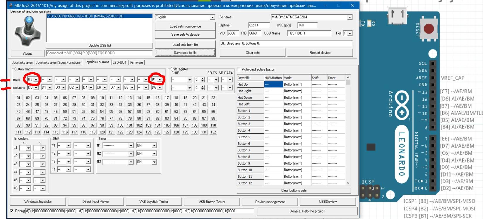 KB
Last edited by Kbird; 01/25/17 07:33 AM.
|
|
|
#4330550 - 01/23/17 02:57 AM
Re: F16-FLCS + TQS (Original) USB Conversion
[Re: Viper1970]
|
Joined: Dec 2016
Posts: 454
Kb1rd1
Member
|
Member
Joined: Dec 2016
Posts: 454
|
Hello Kbird,
I have the F22, but haven't opened its grip until now. I think it has the same shift register as the FLCS. Only thing I've seen, is that the main pcb in the base are different between the F22 and the FLCS. The FLCS has the one which looks like a set square, while the one of the F22 is more like the one which is used in the Cougar (shaped like a simple square).
The picture Sokol showed, is the same principle as my grips are wired, except the go to the original Thrustmaster base pcb thru a 25pin parallel connector instead of a Plasma board, which sits in my cockpit and not in the sticks base anymore. I go this way to make my grips in the pit interchangeable. First I wanted to use a shift register for each handle, but due to some pros for my hardware setting and some other reasons ( only have a limited number of shift registers, but want to be able to built more handles in future) I decided to do it this way. Only drawback is the huge number of cables you have to solder to the connectors. Thankfully the FLCS has Shift Registers so it was Easy ....no Button Matrixes or Diodes for me to worry about , I think I know why some people didn't put Diodes in their TQS's , I may have to stick to building Houses for a Living as my E.Eng. so far is lousy.... Lucky I don't have your Dream of a "Pit" and 8 different Controllers , though I did just buy a FLCS+TQS for $50 today and he threw in a pair of CH Pro Pedals, a CH Pro Throttle and a joyswitch box and some cables for another $25... it was all I had on me , so a good deal I think especially since it was all in more than excellent condition , it looks like it was barely used , I'm not sure if the Pro Throttle even got out of it's Box it still has the twist ties on it , and none of the Manuals even look like they were Read. Have to thank SolderMonkey for telling me to look on Ebay for 2nd hand Thrustmaster stuff  KB.
|
|
|
#4330551 - 01/23/17 03:00 AM
Re: F16-FLCS + TQS (Original) USB Conversion
[Re: undefined]
|
Joined: Dec 2016
Posts: 454
Kb1rd1
Member
|
Member
Joined: Dec 2016
Posts: 454
|
Sokol's Pics are what I have , except In the 1st pic I don't see a PCB with S.Reg. Just a side note: the first pic that Sokol posted is of an F-16 FLCS grip; it was rewired (along with the TM TQS and the analog CH Pro Pedals) directly to a Beta Innovations PlasmaV2 controller board. The mess of wires is because the Plasma had more than enough button and analog inputs and also because it was my first such project . I'm surprised that you managed to find the photos, it was so long ago - 10 years, at least. Edit: I actually still have the PlasmaV2 board (the other hardware is long gone) - it was made in 2004. I think Sokol1 has lots of images on his HD, as I see him posting in many of the Joystick Modding Forums and helping people out
|
|
|
#4330552 - 01/23/17 03:01 AM
Re: F16-FLCS + TQS (Original) USB Conversion
[Re: Kb1rd1]
|
Joined: Nov 2001
Posts: 3,955
Sokol1
Senior Member
|
Senior Member
Joined: Nov 2001
Posts: 3,955
Internet
|
You guys are using BU0836 Diode Matrix as reference for MMjoy2, not sure if is the same thing - can use different diodes orientation, look a CodeGoogle page. That section of MMJoy2 only shows (2) 10 input lines even though it supports 132 buttons.
I think is not 132 buttons but 124: 100 buttons = 20 Rows x 10 Columns + 12 buttons for 6 Encoders (2 per Encoder) + 8 buttons for Shift + 4 buttons for Hat 124 buttons
|
|
|
#4330553 - 01/23/17 03:10 AM
Re: F16-FLCS + TQS (Original) USB Conversion
[Re: Sokol1]
|
Joined: Dec 2016
Posts: 454
Kb1rd1
Member
|
Member
Joined: Dec 2016
Posts: 454
|
You guys are using BU0836 Diode Matrix as reference for MMjoy2, not sure if is the same thing - can use different diodes orientation, look a CodeGoogle page. That section of MMJoy2 only shows (2) 10 input lines even though it supports 132 buttons.
I think is not 132 buttons but 124: 100 buttons = 20 Rows x 10 Columns + 12 buttons for 6 Encoders (2 per Encoder) + 8 buttons for Shift + 4 buttons for Hat 124 buttons Honestly not sure , I just see 132 buttons on the Button Tab ,(firmware 2016-11-01) I thought it supported a 10x10 Button matrix (100) plus the 32 Buttons Windows (DirectX) sees as Hardware Buttons. It was just an Diode/Hat image I found online , but I did notice it was for the Bodnar BU Chip but I wasn't sure if it was the same setup for the Leonardo/ProMicro? it is what I thought you had posted for me before though , that the Diode should point to the Row Wire. How in MMJoy do I program the Matrix , do you know a Tutorial for that? Thanks... KB.
Last edited by Kbird; 01/23/17 05:49 PM.
|
|
|
#4330579 - 01/23/17 07:33 AM
Re: F16-FLCS + TQS (Original) USB Conversion
[Re: Kb1rd1]
|
Joined: Sep 2014
Posts: 33
SolderMonkey
Junior Member
|
Junior Member
Joined: Sep 2014
Posts: 33
Ari-freakin-zona
|
Ok - switch matrices are pretty much all the same. If they work on the 386 board, they'll probably work in MMJOY. Column wires. Row Wires. They intersect at a switch and diode. BUT the polarity of the diode has to be consistent throughout the matrix. All the bands point toward the row wires or all the bands point towards the column wires. Whatever you want to call them. in MMJoy you have the luxury of if you screw of the diode polarity, but the polarity remains consistent... you can just reverse the Row and Column selections in software and be good to go. The diodes flow through the switch as if they are sliding along the wire to the other side of the switch.  Programming a matrix is just setting the Rows and Cols. To further disgrace your image...  This is a 4x2 matrix setup with 4 Columns and 2 Rows. The Row lines are separate in Gold and Gray. The Column lines are duplicates. They can join color to color anywhere - on the switch, on the control board or you can Y them along the way. As long as the diode is on the switches, and the band points the same way, in this case cathode band towards the row lines, the matrix can work. BUT if you screw up the polarity and can't see any switch action when you set it up, flip the rows and columns in MMJoy setup. As per my usual disclaimer ... I am not an artist.
|
|
|
#4330598 - 01/23/17 12:19 PM
Re: F16-FLCS + TQS (Original) USB Conversion
[Re: Kb1rd1]
|
Joined: Nov 2001
Posts: 3,955
Sokol1
Senior Member
|
Senior Member
Joined: Nov 2001
Posts: 3,955
Internet
|
Honestly not sure , I just see 132 buttons on the Button Tab ,(firmware 2016-11-01) I thought it supported a 10x10 Button matrix (100) plus the 32 Buttons Windows (DirectX) sees as Hardware Buttons.
Looking at MMJoyJoySetup (01-11-2016) is listed 128 buttons + HAT, so is 132 buttons like you say. Just don't see where connect all this. BTW - The buttons that Windows see (up to 32) is dependent of Diode Matrix or Shift Register like the rest. Mega_MOzg suggested Diode Matrix is similar to Bu0836 one - diode toward Rows (lines). 
|
|
|
#4330734 - 01/23/17 06:44 PM
Re: F16-FLCS + TQS (Original) USB Conversion
[Re: SolderMonkey]
|
Joined: Dec 2016
Posts: 454
Kb1rd1
Member
|
Member
Joined: Dec 2016
Posts: 454
|
Editted by Kbird in Red+Bold, scroll this quote box if needed....Ok - switch matrices are pretty much all the same. If they work on the 386 board, they'll probably work in MMJOY. Column wires. Row Wires. They intersect at a switch and diode. BUT the polarity of the diode has to be consistent throughout the matrix. All the bands point toward the row wires or all the bands point towards the (switch) on the column wires. (See Image) Whatever you want to call them. in MMJoy you have the luxury of if you screw of the diode polarity, but the polarity remains consistent... you can just reverse the Row and Column selections in software and be good to go. The diodes flow through the switch as if they are sliding along the wire to the other side of the switch. Programming a matrix is just setting the Rows and Cols. To further disgrace your image... This is a 4x2 matrix setup with 4 Columns and 2 Rows. The Row lines are separate in Gold and Gray. The Column lines are duplicates. They can join color to color anywhere - on the switch, on the control board or you can Y them along the way. As long as the diode is on the switches, and the band points the same way, in this case cathode band towards the row lines, the matrix can work. ( KB... even though the cathode (stripe) is on the column wire it is still "pointed to the Row wire (through switch) hence it is correct pointed at the switch) BUT if you screw up the polarity and can't see any switch action when you set it up, flip the rows and columns in MMJoy setup. As per my usual disclaimer ... I am not an artist. Future Readers Quote above edited for important points....scroll through it Thanks Solder Monkey , your Images made my "LightBulb " go off as I said earlier I am very "Visual", so I now "see" your explanation, (ie: slide the diode along the wire to the other side of the switch). Also If you didn't see the other post ,thanks for telling me to look on Ebay, I got a good deal I think this weekend on some Retro Sim Gear ...essentially a new FLCs+TQS ,CH ProPedals and Pro Throttle, for $75, they even came with the Manuals and Orig. Floppies It looks like I got it right with physical testing, but nowhere in my reading the last few months did I see anyone mention the small bare connection wire on the ANT double Pot/switch . I knew I had a short or issue somewhere as none of the switches worked at 1st and some didnt have diodes (T6) so I knew that wasn't the issue, so I dismantled the TQS so I could get a better look at everything , it was then I noticed the small bare wire, as previously it was on the back side of the pot and 1/2 still in the handle, at 1st I thought it was a strand of solder and an accident, but the Soldering Iron didn't budge it, so I used my Clippers and the ANT T6 SWTH immediately started working so I knew I was on the right track. What was once a TQS (heat shrink not done yet as still testing)   THE OFFENDING WIRE ...as the other side of T6 Switch was also common to all switches  KB.
Last edited by Kbird; 01/23/17 06:58 PM.
|
|
|
#4330748 - 01/23/17 07:24 PM
Re: F16-FLCS + TQS (Original) USB Conversion
[Re: Sokol1]
|
Joined: Dec 2016
Posts: 454
Kb1rd1
Member
|
Member
Joined: Dec 2016
Posts: 454
|
Honestly not sure , I just see 132 buttons on the Button Tab ,(firmware 2016-11-01) I thought it supported a 10x10 Button matrix (100) plus the 32 Buttons Windows (DirectX) sees as Hardware Buttons.
Looking at MMJoyJoySetup (01-11-2016) is listed 128 buttons + HAT, so is 132 buttons like you say. Just don't see where connect all this. BTW - The buttons that Windows see (up to 32) is dependent of Diode Matrix or Shift Register like the rest. Mega_MOzg suggested Diode Matrix is similar to Bu0836 one - diode toward Rows (lines). - Oh Wow , I maybe stuck if you don't know how to assign the Button Matrix in MMJoy2 being one of the Guru's around here , I am trying to find old Mjoy or Mjoy16 Manuals as I now think that Mega-Mozg continued on the work from those projects, and it maybe why there is limited Documentation for MMJoy2. - Mega Morg's Fritzing images didn't make sense to me at 1st as (in my case anyway) the ROW wires are Common wires to all switches so I didn't see how diodes could be on every switch and still on a common wire but I now realise the diode can be solder right to the switch and the common wire to the diode at each switch after looking at some sites about making your own Keyboard like at Deskthority , I founds these image there .... Row diodes on homemade Keyboard  And the Columns done too...  KB.
Last edited by Kbird; 01/23/17 07:24 PM.
|
|
|
#4330756 - 01/23/17 07:55 PM
Re: F16-FLCS + TQS (Original) USB Conversion
[Re: Kb1rd1]
|
Joined: Dec 2016
Posts: 454
Kb1rd1
Member
|
Member
Joined: Dec 2016
Posts: 454
|
So I found some old PDF's etc of MJoy16-C1 User�s Manual , and they include the wiring etc ( the pics/diagrams of wiring direct to a Mjoy16 Board show how with Arduino too) but MMJoy2 button Matrixes are programmed differently it appears... Mjoy16_C1- PDF V1.1 From the Above incase it is no longer available.......... About use of diodes and their polarity All diodes shown in below sections are required to eliminate so-called �Phantom-Buttons� effect which occurs in matrix key layouts when three or more buttons are pressed simultaneously. They are already included on the Key Matrix board. If you are using the Key Matrix board then don�t bother reading this section. The diodes shown are widely popular 1N4148 but may be any other type of low power fast switching diodes. Since diodes are asymmetric devices it does matter which way you connect them. The black band shown on the diode in below illustration corresponds to polarity marking of 1N4148:  This band colour may be other colour depending on typical body colour of the diode. Other types may have different marking convention. If you are not sure about the polarity of diodes you have you can easily test find this out by simple test described below: 1. Connect MJoy16 to PC via USB cable. Don�t connect any digital controls yet. Make sure that Windows has installed the MJoy16 and open Game Controllers panel for �MJ16�. This is done via Control Panel in Windows. 2. Take two wires Row A and Column 1 from MJoy16 digital inputs connector. When you connect these two wires together you should see Button 1 lighting up on �MJ16� panel. 3. Place the diode you have between these two wires in one or other way. When Button 1 lights up again make a note of the diode marking and remember this position as a reference. 4. When wiring all other controls use this reference to place all other diodes the same way. Wiring digital controlsIf you don�t use Key Matrix board you will have to solder diodes directly to pushbuttons and switches. These diodes are necessary to avoid so-called �Phantom Buttons� presses. They should be soldered directly next to each button control. Below are some examples how pushbuttons and toggle switches are wired directly to MJoy16 board:  Wiring pushbuttons Wiring pushbuttons If you don�t use Key Matrix board you will need to solder a diode in series to one of the pushbutton pins. A wiring example is shown below: 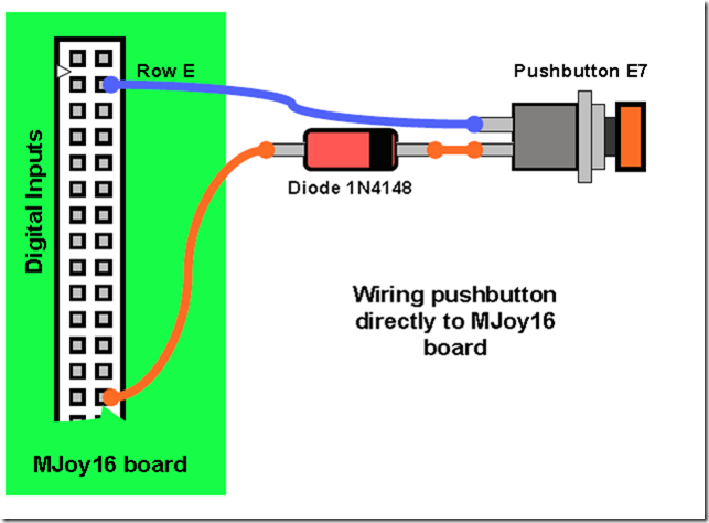 Wiring toggle switches Wiring toggle switches Toggle switches can be single throw or double throw. MJoy16-C1 is mainly designed for single throw toggle switches but double throw toggles may also be used if required by your cockpit application. Single throw toggle switches have two positions: �On� and �Off�. Single throw toggle switches are wired exactly as pushbuttons so please refer to pushbutton wiring description for wiring the single throw toggle switch. Double throw toggle switches have three positions: �On1�, �Off� and �On2�. �Off� is the middle position. These toggle switches use 2 pairs of contacts on keys matrix. The principle of connecting them is that common pin is connected to Column signal wire and the other two pins are connected to different Row signal wires. Below is example of wiring double throw toggle switch without Key Matrix board:  Wiring rotary switches Wiring rotary switches Wiring of phase shifted rotary switches is similar to wiring of double throw toggle switches. The first thing is to find out which pin on the rotary switch is common. Its position depends on the type of rotary. On some rotary switches it may be in the middle but some may have it on one side. Below is an example how to directly wire a rotary switch to the MJoy16 board:  Wiring Hat switch Wiring Hat switch Hat switch is 8-way hat switch and it is made of 4 microswitches arranged on 4 sides of hat switch enclosure. A small joystick handle presses one or two switches at a time depending on angle of deflection. When only one switch is pressed it gives four main directions at 90 degrees angles: �UP�, �RIGHT�, �DOWN� and �LEFT�. When two switches are pressed it gives intermediate directions: �UP-RIGHT�, �UP-LEFT�, �DOWN-RIGHT� and �DOWN-LEFT�. Below is a diagram showing how to wire the hat switch directly to the MJoy16 board: 
Last edited by Kbird; 01/23/17 08:46 PM.
|
|
|
|
