homepage
F16-FLCS + TQS (Original) USB Conversion
Posted By: Kb1rd1
F16-FLCS + TQS (Original) USB Conversion - 12/28/16 07:06 PM
F16-FLCS + TQS (Original) USB ConversionI am planning to Convert my gameport F16-FLCS + TQS (Original) to USB along with my CH Pro Pedals after reading the MMJoy2 Thread and posting a few questions there but thought I should start another thread here , so as not to clutter up that thread , so I will copy some of that info over here too but 1st
many thanks to Mega_Mozg_13 and Sokol1 to start.
The MMJoy2 Main Thread with Links to MMJoy2 Firmware etc is over Here:
http://simhq.com/forum/ubbthreads.php/topics/4322189/1My 1st Post on page 109 :
http://simhq.com/forum/ubbthreads.p...uild-your-own-usb-controller#Post4322189FIRMWARE DOWNLOADS PAGE ...try 2016-8-18 it has the least bugs currently....... page is in Russian but I don't think you need to translate to see Dates
Direct link to 2016-08-18 Update1 file FW LINK ALL FIRMWARE DOWNLOADS I have been gathering Info and Pics from Numerous places to start this Process , so I'll add that Info in posts below and try and add Ideas and Pics of my own as I go , but any ideas or suggestions will be greatly appreciated .
I am planning on using a Clone Leonardo Board ($12-15 each) in both the TQS Base and the F16-FLCS Base to help simplify this for myself as I don't do electronics as a hobby or otherwise, though I have plenty of experience with Tools and Soldering, and have bought myself a Hakko FX-888D and a couple of Tips for it and have to say it is a nice quality Tool which I appreciate, but it isn't really needed though Temperature Control and fast heat up is nice after years of a standard 25w Stick Soldering Iron ( now with a bad tip

)
The Leonardo I already have , I had issues with it's Reset Button not initiating the Boot Loader Mode , this maybe because when I got it I loaded the Blink Sketch from the Arduino IDE (1.6.3) per the Arduino Website Leonardo Setup Tutorial, and thus the Computer is constantly polling the Leo running the Sketch and apparently did not "see" the Reset Command , so the Reset button would not "reset" the Leonardo to bootloader mode. It would disappear (per the MMJoy2 Wiki) but almost instantly reappear on the same Com Port. But reading about the GND and RESET Pin on the Arduino Pro-Micro and touching it's GND and RESET Pins twice quickly to do it, gave me the idea to quickly push the Leonardo Reset button quickly twice and it worked ! and gives me 5-8 secs to hit the Firmware download button in MMJoy2 now.
***Update*** My extra Kuman Leonardo Clone Boards arrived from China (only one week excellent time) and I did not load the Arduino Blink sketch as I did on the Original Leonardo ( per Arduino instructions) and both boards instantly showed me the Bootloader Com Port after hitting the Reset Button the 1st time, and I loaded MMJoy2-2016-11-01 with no issues unlike the 1st time and then programmed two axis and changed the USB VID and PID and name on each one so windows sees them differently , again with no problems unlike the Original Board , so I think the Trick is NOT to load any other Code to New Leonardo Boards before you Upload the MMJoy2 Firmware ,as it seems to cause issues with the USB Port as it is being constantly Polled by the Blink Sketch that is already in the Firmware causing an issue for MMJOY2 , the Arduino 1.6.3 IDE , does not have any issue finding the Bootloader Port itself BTW , it scans for the Bootloader Port and then uploads , MMJoy2 does not do this.
KB
On the Hardware front
Sokol1 has pointed out that both the FLCS and TQS PCB Boards get totally removed from the Bases and are not reused at all in the Conversion along with a lot of the Wiring in the Bases needing Changing or replacing , this makes room for the Leonardo Boards that will take over all the old PCB Functions so it does not matter if you have the Original FLCS Chips (v3.04/3.08) or the Stickworks Digital Chip Upgrades that came out in about 2000 as the Original PCB is not used at all.
The Wiring and PCB inside the FLCS Handle is KEPT , the PCB already has 4021 Shift Registers for the Buttons etc to reduce the number of Wires needed and so it can be reused as is by connecting 4 Wires to the ICSP Header and the red to an AI pin on the Arduino.
On the TQS the Thumb Eraser Button (mouse emulation) must be replaced along with it's wiring , I plan to use an extra FLCS Hat Switch since I have some in a Repair Kit I bought many years ago from TM and it seems to fit kinda Ok in the hole left by the Eraser Button box which can be removed in one piece easily. I won't be saving the Tac. Switch (small white button) but you could if replacing the Eraserhead with a small PS2/3 Joystick button or similar perhaps.
I am going to Connect the CH Pro pedals to the TQS after rewiring them totally to Work in Plane Mode Only since I also have an old TM Racing Set I can convert if needed. There is no PCB to worry about in the pedals, it is all direct wired to the Leo. I am going to use and old Gameport Cable to connect between the Pedal and TQS, since I have it and reuse some Gameport male and female Header plugs in an old JoySwitch Box I had stored with my FLCS/TQS Combo ,since I want them to be detachable if needed.
I am planning on Using the TM MFD's (USB) as well so at this point I won't be adding a multitude of new buttons to my TQS or FLCS, like some have done , unless I find issues with the TM MFD's.
My FLCS Rubber Boot's Retaining Ring are damaged (cracked) so at the moment, I think I will move the FLCS Handle after some modifications, to the Base of an Old gameport TM X-Fighter JoyStick I also have since it appears to have a nice spring/gimbal setup and to my surprise a metal plate for it's base unlike the FLCS, which adds some nice Weight to it. It will take a bit of modification, as the shaft is too long and has a square notch but I think it will work fine ? but I have not researched the Pots in it yet, so I'm not sure if I need to swap them over to the FLCS ones too?
I will update this thread as I go hopefully and save a post or two below this one , so I can add pics and updates later hopefully.
Thanks for Reading this and Helping out...
Kbird.
.
Posted By: Kb1rd1
Re: F16-FLCS + TQS (Original) USB Conversion - 12/28/16 07:07 PM
Posted By: Kb1rd1
Re: F16-FLCS + TQS (Original) USB Conversion - 12/28/16 07:07 PM
BUILD / CONVERSION Pics....I have posted Pics throughout the Thread as I went actually , as I asked questions and others helped , If there is a pic of something particular you need post a message or PM me...
THE ATTACHED FILES ARE HOW I USED MMJoy and the LEONARDO PINS
KB
Posted By: Kb1rd1
Re: F16-FLCS + TQS (Original) USB Conversion - 12/28/16 07:50 PM
The Good INFO From the MMJOy2 Thread so you don't need to hunt for it - I currently have nothing attached to the Leonardo , which may explain the error? I am just starting this endeavor as I have a gameport FLCS16+TQS and CH Pedals that I have had for many years (nearly unused) with the Stickworks Digital Chips installed , though I still have a number of the Old Chips as well as some new TM Pots and Hat Buttons I got before TM stopped selling them.
- If I remember correctly Windows only recognize joystick that has at least 1 or 2 axis.
And when make modifications in previous configuration (axis, buttons) hit the "Clear settings".
Convert F-16 FLCS will be easy, just wire the axis, and the Shift Register board inside grip to MMjoy2.
For throttle is more easy reuse the existent diode matrix
The "eraserhead" "IBM mouse" (under thumb finger) need be replaced with min-stick or HAT, their serial protocol is not compatible with MMJoy2.
- You were right Sokol1 , once Windows had 2 AXIS (X+Y) assigned JoyCPL started working without the Error above , assigning one button per the FAQ didn't work for some reason. Of course nothing is attached yet so not really working but slowly getting there thanks.
I have been reading the thread since last week , so I have picked up some 74HC165 SReg ,MCP3208 chips and 1N4148 diodes already , just not sure how I'll use them yet , still looking for pics of schematics etc before I get to far into this and ruin something by accident. smile
KB
------------------------------------------------------------------------
- I think diodes should be added. My TQS had none
- Where should diodes go in the TQS ? do you mean putting 1N4148 diodes on the buttons for the matrix I was just reading about to stop ghosting? does anyone have Schematics for the FLCS+TQS Wiring perhaps ?
Thx,KB.
- Think in diodes in this way: One diode in one of 2 pins of each switch or HAT (HAT are just 4 switches around a pole). Then became easy. smile Or, for example using a breadboard for put the diodes side at side, and wire buttons and HAT there.
-----------------------------------------------------------------------
Do you add the 1N4148 Diode to one of the Button wires in the TQS Handle ? which one ? or does it matter ? or best to do it in the Base just before the Arduino ? ( I have read in the thread that this is for debouncing the buttons and a Hat is really 4 buttons,so I already bought some)
- In what pin of button put the diode don't matter.
- In HAT you will notice 4 wires and one common - because there are 4 switches internally, in this case put one diode in 4 individual wires.
- You can put the diodes in a breadboard on base, but in this case you need run 2 wires for each button on grip.
The diodes in buttons save some wires, but require more attention with wire order.
- The diode don't need by exactly in the switch pin, can be in middle of the wire running for then, if switch are in difficult to access place.
- Thanks , more good info , I did not realise from the reading I needed a Diode on EACH switch in the POV HAT, ie I wasn't thinking about them as 4 individual switches, one for each direction , so one diode on all 4 wires ...lots of Soldering to do then , I'm glad I got a good Soldering Iron after all these years with a Fine Tip as there appears to be 19 wires in the TQS Handle , not sure what is what yet though.
---------------------------------------------------------------------------------------------------------
- mmjoy support only 74HC165 and 4021 shift register.
- and use 1N4148 diodes on the buttons (or button matrix) to stop Ghosting
-----------------------------------------------------------------------
- Since Arduino are cheap, one in each device make thighs more easy to do.
And you get a more flexible set, can use the throttle with other joystick for example.
You can connect the CH pedal - need add a 3rd wire in their pots - to throttle or joy base.
More easy in joy because there are a DB-15 female connector that you can reuse, or migrate this connector for throttle base.
Until now no one did a steep by steep tutorial for do this, since are several ways to do. Maybe you will make the first? smile
In FLCS probable you don't have to change nothing in grip, so is just mater to install Arduino in base - even no need these shield PCB, just a support for then is too small and don't have holes for fix. Easy to do.
Wire the 2 pots and the 6 wires coming from Shift Register on grip.
The ease way to do this is... start make.
- Thanks Sokol1 , I will order some cheap Clone Leonardo's from Amazon , it will take a few weeks from China but I have lots to learn and figure out before they get here anyway smile I could not find a good tutorial for the Bodnar BU USB Connector Boards either when I looked last (surprisingly little help on his site), that why I decided to try MMJoy2 and Arduino since there seems to be good Community Support smile
I have the Original TQS , not the Cougar TQS , so I am not sure what is in the Handle yet , but the F16_FLCS and the Pedals used to attach to it via gameport connectors , The F16_FLCS does not have any extra gameport connectors , just the Old AT Style Keyboard connectors for Input and output (cord which I never cut off) , maybe the F22 Pro did? There is also the DB9 Connector for the Serial Mouse / Cursor Control (which I need to change to a button) . Mot sure If I can reuse some of the Wiring for things as yet.
Not sure what is in the Handle of the FLCS_16 either yet either as I have only opened the base on it and the TQS so far , I am hoping for the Shift register but that may be only in the F22 Handle?.
Thanks for the Info on converting the CH Pro Pedals that will be very handy , not my favorite Rudders (too narrow) but they may have to do for now since I already own them and a set of Gameport TM T2 Racing Pedals and Wheel.
Thanks for your Help and Advice so far .... and Merry Christmas.
- OK, I forget that F16FLCS/22PRO connect to TQS and not the contrary (have one these last there, in the shelf at more than 10 years, not fan of F-16 grip).
But you have two options to connect the pedal, reusing the original cables. In TQS or in F16 in this case using the PS2 cable fitted inside pedal cutting one end or installing there a correspondent PS2 connector, the cable has 5 wires internally and is what you need for pedal:
X, Rx, Rz axis, +5V, GND.
Or in TQS, in this case using the DB15 cable of pedal. What you need change inside pedal is:
The pot's is wired with two wires (as resistance), but for USB you need 3:
+5V
Signal
Gnd
But usually this gameport cables has several wires internal, and if need the external mesh over internal cables can be used as Gnd.
In F16 grip has a Shift Register board internally, basically the same of F22 PRO, Cougar or Warthog.
The basic difference between F16/F22 TQS and Cougar TQS is:
Cougar is made in Zamac (cheap metal that can broken is fall on ground), use more cheap potentiometer in throttle axis, their "TDC" is a mini-stick (F22 TQS is mouse for laptop) and has no circuit internally, only a diode matrix.
---------------------------------------------------------------------------------------
- Hi, I did converted TM FLCS and TQS to USB with 2 Arduino Pro Micro. FLCS had shiftregister, that I did damage so I had to do a diode matrix. Inside TQS you only have to add diodes to each switch... and connect them. I replaced the rubber thumb thingy with a PS2 ministick. Good luck!!
---------------------------------------------------------------------------------------
- But TQS don't has Shift Register (or is integrated in main PCB...).
The easy way is, remove all that have internally, the "laptop" mouse, leave the small button bellow, add one diode in each switch. Not difficult if you plan what do first.
BTW - Eventually, If need you can buy potentiometers from CH - cost ~10$, and use in F16 and TQS, they have same format and values, is too made by CTS, but CH models has better quality.
But TLE501x contactless sensors work better and cost less
-------------------------------------------------------------------------------------
-
Communication between F16 and TQS when connected the old way --- FLCS>RDDR>TQS.If place the MMJOy2 inside TQS will be required for F16
+5V
Gnd
X input
Y input
4 other TLE501x inputs - can be shared between 2 axis.
3 inputs for Shift Register, besides the shared +5V, Gnd
Total of 11 wires.
If MMJoy2 is placed on F16:
+5v
Gnd
Throttle input
Range input
Ant input
X in mini-stick if used
Y in mini-stick if used
10 buttons - 2 x 5 matrix = 7 wires
Total 14 wires
or if not used mini-stick but HAT - 3x5 matrix = 8 wires
Total 13 wires
The others connections are one HAT (COMM) and some press or toggle switches, just require buttons inputs, and as they are few can be wired with diode matrix (row x columns), e.g. 2x5.
-------------------------------------------------------------------------------------------
- The Keyboard Cable and port on the F16 FLCS is actually AT style , not PS2 but the number of wires is the same I think? 5 , but I think I will Wire the FLCS as one Joystick and the TQS and Rudders connected as another , so I was thinking I could just use the original Rudder to TQS Gameport plug ? but perhaps not, it may need a direct Wire Connection to the Arduino so I would need to add a 15pin Game Port Connector with accessible soldering points.
The format PS2/DIN or DB15 or DB9... don't matter if has the number of pins and wires you need for plug the pedal. You need 5 wires for pedal, study what connector will be more convenient use.
*** Edit ..maybe I misunderstood ? .... more reading and now I think I am not reusing the TQS or FLCS Circuit Boards at all , everything is wired to the Arduino in each base instead.
Yes, only reuse the Shift Register board in the FLCS grip and it's wiring, you need to remove all other boards.
So both TQS and FLCS PCB's are taken out of their Bases to make room for the Arduino Boards ...Thanks for that clarification too...
-----------------------------------------------------------------------------------
- This joy & throttle combo need a USB controller with at least 5 axis:
2 for joy X, Y, 1 for throttle, 1 antenna, 1 for range.
Or 7 if you plan use a PS2 mini-stick (2 axis) for replace the "IBM" mouse under thumb in throttle leaving the TQS like Cougar TQS.
The only part of original electronics that you will reuse is the Shift Register board inside F22 grip.
Remove the other circuit boards but leave buttons, HAT, wires and his connector in place.
- The ANT and Range and mini joy pots how connect this PCB?
In TQS the ANT is just a conventional pot, require 3 wires +5V, Gnd, signal.
- The Range pot is not a double stacked pot - ie. 2 pots in one axis
On The Range Pot , the one near the shaft is actually a switch. The one at the bottom is the pot.
See the switch has 2 terminals and the other 3.
---------------------------------------------------------------------------------------------------
KB.
Posted By: Kb1rd1
Re: F16-FLCS + TQS (Original) USB Conversion - 12/28/16 08:56 PM
Posted By: Kb1rd1
Re: F16-FLCS + TQS (Original) USB Conversion - 12/28/16 09:05 PM
MY PERSONAL CONVERSION NOTES
a bit rough as hand written, as they were for my own use but I thought perhaps someone else may find some of it helpful in the Future.....
KB.
Posted By: Sokol1
Re: F16-FLCS + TQS (Original) USB Conversion - 12/28/16 10:17 PM
Kbrid,
Nice start, very detailed tutorial.
My FLCS Rubber Boot's Retaining Ring are damaged (cracked) so at the moment, I think I will move the FLCS Handle after some modifications, to the Base of an Old gameport TM X-Fighter JoyStick I also have since it appears to have a nice spring/gimbal setup and to my surprise a metal plate for it's base unlike the FLCS, which adds some nice Weight to it. It will take a bit of modification, as the shaft is too long and has a square notch but I think it will work fine ? but I have not researched the Pots in it yet, so I'm not sure if I need to swap them over to the FLCS ones too?
X-Fighter use the same base of F22PRO, but the gimbal in this base, in both stick use very heavy torsion springs, depends on game preferences maybe you will prefer the F16FLCS gimbal. Anyway look in F16FLCS fit inside X-Fighter base, since this is more heavy and result a more stable stick.
This "box converter" is for Cougar TQS, connect reusing their Diode Matrix:
http://simhq.com/forum/files/usergals/2016/12/full-40431-130671-tqs2_to_usb.jpg
Posted By: Kb1rd1
Re: F16-FLCS + TQS (Original) USB Conversion - 12/28/16 11:17 PM
Hi Sokol1 , yes thanks to you and your many posts over the years here and elsewhere , I am finally working on it
I did not know the base for the X-Fighter was the same as the F22Pro but yes it has a big coil spring in it rather than the 2 smaller springs of the FLCS, seems nicer to me and I don't ever remember using it much it was just for ouick flying without programming everything on the FLCS+TQS combo , so it should be in good shape and the mods don't appear to be too hard.
I was looking at the TM Hotas X (Hotas 3)Joystick (available separately too) and it appears to have the same boot retaining rig as the FLCS but it is metal , so I guess they finally fixed that issue , maybe I should of bought one of them and gutted it for Conversion use instead
I have started dissembling everything including the Pedals ,and will start converting/rewiring them 1st since that is the easy part and good practice for the rest I think.
KB.
Posted By: Sokol1
Re: F16-FLCS + TQS (Original) USB Conversion - 12/29/16 12:55 AM
Posted By: Repvez
Re: F16-FLCS + TQS (Original) USB Conversion - 12/29/16 04:00 PM
This is how I would like to convert:
one pro micro panel for both device (FLCS+TQS) and put in the TQS base.
So I Should be :
1 shift reg in the FLCS handle
2 TLE5010 PCB
1 base PCB ( which collect the shift reg and X,Y axis TLE5010 wires and led to TQS)
If I count well this 14 wires , so I can use the original DB15 connector to connect from FLCS to TQS
In TQS:
1 TLE5010 PCB for Z axis
1 shift reg in TQS handle
1 pro micro shield (where put in connector from FLCS and Collect the TQS wires and there would be an extra connector for rudder TLE5010 and other additional buttons)
I don'know, how can show properly this schematic
this method only need one USB connection for PC and the MMjoy program set up is much more simpler.
Posted By: Sokol1
Re: F16-FLCS + TQS (Original) USB Conversion - 12/29/16 06:27 PM
If you want the controllers tied together, put the controller in joy base.
This means small length of wires for the most important axis, X and Y.
Use the big wires ~1,5 meter - for throttle axis, less important.
More length the wires more tendency to pick noise.
Just invert the planed boards places.
BTW - Picture (from il-2(ru) of (F16/F22) TQS converted (standalone) for USB - in this case using DIY MJoy16 ("Grandfather" of MMJoy2).
Notice that the cable (multicolored wires) coming from grip was not changed, and although inside grip is not showed, there as simple matter of cut the wire coming for one pin of each button and add a diode. This is (IMO) the more easy way to do.
 jpg images
The diodes in PCB on base is for the extra buttons installed in base case.
Posted By: Kb1rd1
Re: F16-FLCS + TQS (Original) USB Conversion - 12/29/16 11:21 PM
That is a nice conversion Sokol , looks like Mega_Mozg is as good on the Hardware side as he is on the Software , at least I think it is him , I don't read Russian
KB.
Posted By: Viper1970
Re: F16-FLCS + TQS (Original) USB Conversion - 12/29/16 11:45 PM
Hello Kbird,
the X-Fighter uses a different base from the F22 Pro. It has normal springs not the torsion springs and the mechanics are made of plastic. But it's in my opinion the best base original Thrustmaster ever has made. I have three of them here. I love this stick, and it's also the only 1:1 copy of an B8 standard flight grip you could get. All others from Thrustmaster like the old FCS, PFCS and the later TopGun aren't the right size.
But back to the base, just remove the springs inside and you have a relatively good feedback from the stick for flying. No more hard centering. The stick centers over other mechanics beyound the dust cover. Could be a little stronger, but for my opinion a real good feeling. I hate the centering of most flight sticks and never found any good solution from any company. Some say that the saturn ring mechanics is real good (Suncom Hawk, Talon and Eagle) but it's only great moving it around the corners, cause it has also the same "latch back to center" problem.
I use the X-Fighter bases in my cockpit for my selfmade side- and center-stick controllers. I have also connected a rubber boot from a canibalized HOTAS-X to the X-Fighter base. The ring around the boot and the boot itself is much better.
I have 12 FLCS here and none of them has an intact ring around the rubber. The plastic it is made of, is very poor quality and they used electric drills to put the HOTAS together. Many of the screw connections are broken even if the sticks are in original mint condition. Same is with the TQS.
Posted By: Kb1rd1
Re: F16-FLCS + TQS (Original) USB Conversion - 12/29/16 11:56 PM
Posted By: Viper1970
Re: F16-FLCS + TQS (Original) USB Conversion - 12/30/16 12:08 AM
Have made an extra nozzle control for CAP2 at my TQS, but I hadn't the time to test the sim. But it looks real good and the flight behavior should be relative realistic, as far as I have read in some reviews.
Posted By: Kb1rd1
Re: F16-FLCS + TQS (Original) USB Conversion - 12/30/16 12:16 AM
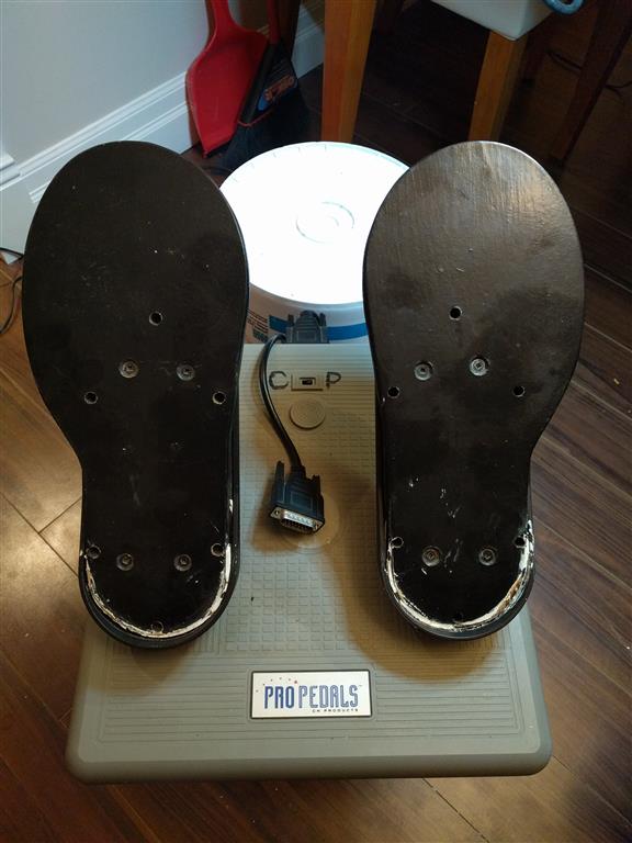
Started on the CH Pedals, Undid the 15 Base screws and lifted it off only to have all the springs pop off etc, it may have been smarter to flip it back over 1st had I known , but it shouldn't be an issue I don't think.
Since I have it apart I have added new Feet to it to stop it sliding (always an issue) but also to stop some of the Flex in the base I seem to remember it had. One thing to note is you can pretty much only add the feet exactly where the CH Engineer's did as any bolts or screws will interfere with the Black Sliding base units for each Pedal.
I used an old 20 pin P.S. wiring harness to get my new wires for the 3 Pots and just used 9 different colours , so what you see colour wise in my Photos doesn't mean anything as far as "Electrical Standards" go , I just need to keep track of the colours myself. *** not sure if doing it this way was a good idea yet as far as getting it all put back together?
I also used an old Computer Case 5.25" Slot Black Cover plate and some 5 min. Epoxy to Fill the Holes left n the TQS Base due to removing the TQS Original PCB.
KB.


Posted By: Viper1970
Re: F16-FLCS + TQS (Original) USB Conversion - 12/30/16 12:17 AM
For the replacing the eraser head mouse you could also use a thumb stick of an old gamepad and connect it to unused axis of your USB-contoller-pcb.
Posted By: Kb1rd1
Re: F16-FLCS + TQS (Original) USB Conversion - 12/30/16 12:21 AM
Hi Repvez , I am new to this too and don't know much about the TLE5010x Chips myself , (I am going to try my Pots and some spares 1st) so I will need to leave help with that to Sokol1.
I also don't plan to join the TQS back to the FLCS as it was done originally , I plan to use a cheap Leonardo Clone in the base of the TQS and another in the FLCS and have them plugged in directly to the computer individually, assuming I can get it all to work that way of course.
KB.
Posted By: Sokol1
Re: F16-FLCS + TQS (Original) USB Conversion - 12/30/16 03:26 AM
Take a look in this CH Pedal 'mod' for remove the center "clunck":
http://imgur.com/gallery/GW6Hl
Posted By: Kb1rd1
Re: F16-FLCS + TQS (Original) USB Conversion - 12/30/16 04:45 AM
Good Find Sokol1
but you just added to my work ...:) I haven't heard about this mod before, but I think I might do it, as it sounds like it makes a difference and I don't want to open these up again that is for sure
KB
Posted By: Kb1rd1
Re: F16-FLCS + TQS (Original) USB Conversion - 12/30/16 05:01 AM
Hello Kbird,
the X-Fighter uses a different base from the F22 Pro. It has normal springs not the torsion springs and the mechanics are made of plastic. But it's in my opinion the best base original Thrustmaster ever has made. I have three of them here. I love this stick, and it's also the only 1:1 copy of an B8 standard flight grip you could get. All others from Thrustmaster like the old FCS, PFCS and the later TopGun aren't the right size.
But back to the base, just remove the springs inside and you have a relatively good feedback from the stick for flying. No more hard centering. The stick centers over other mechanics beyound the dust cover. Could be a little stronger, but for my opinion a real good feeling. I hate the centering of most flight sticks and never found any good solution from any company. Some say that the saturn ring mechanics is real good (Suncom Hawk, Talon and Eagle) but it's only great moving it around the corners, cause it has also the same "latch back to center" problem.
I use the X-Fighter bases in my cockpit for my selfmade side- and center-stick controllers. I have also connected a rubber boot from a canibalized HOTAS-X to the X-Fighter base. The ring around the boot and the boot itself is much better.
I have 12 FLCS here and none of them has an intact ring around the rubber. The plastic it is made of, is very poor quality and they used electric drills to put the HOTAS together. Many of the screw connections are broken even if the sticks are in original mint condition. Same is with the TQS.
Missed this post earlier ....
you have 12 FLCS's ? wow....
I may misunderstand you but my Gameport X-Fighter has the Steel Coil Spring on the Gimbal , not the two smaller springs like in the Original FLCS stick , The X-Fighter is stiffer than the FLCS for sure , though I am not sure which one is "best" ? maybe personally preference I think but I tend to like a stiffer stick , it's why I switched to TM sticks originally as my CH Joysticks were too "sloppy + loose" and didn't give me enough "feedback" for fine control ( or that's what I thought at the time if I remember correctly).
this is mine in bits on the table, I will need to make a notch for the shaft and shorten the top to make the FLCS handle fit onto it though....
KB.

Posted By: Kb1rd1
Re: F16-FLCS + TQS (Original) USB Conversion - 12/30/16 05:11 AM
Have made an extra nozzle control for CAP2 at my TQS, but I hadn't the time to test the sim. But it looks real good and the flight behavior should be relative realistic, as far as I have read in some reviews.
thanks Viper good info , so you added another rotary controller to the TQS to control the Nozzle Angle ?
Which Rotary Controller did you use ? I like that idea... any Pics of it or your Mod?
Thx..KB
**edit: I hope you are right about CAP2 , I decided to add it to my Steam library since it is still on Sale.
Posted By: Kb1rd1
Re: F16-FLCS + TQS (Original) USB Conversion - 12/30/16 05:15 AM
For the replacing the eraser head mouse you could also use a thumb stick of an old gamepad and connect it to unused axis of your USB-contoller-pcb.
Not a Console Gamer at all ...yukkk....
so no broken gamepads here but I have some extra TM Hat switches from the FLCS so I will Use one of them , it fits in the hole and can be held with Hot-Snot if needed I think.
KB
Posted By: Repvez
Re: F16-FLCS + TQS (Original) USB Conversion - 12/30/16 09:36 AM
I changed the earase head stick in my TQS with ps3 minijoy
, but it not a good solution , because it is bigger than should be.
And it doesn't fit together the handle.
Can anyone how put in properly in there? or where can I buy those minijoy what the cougar use it, because there is the microswitch place in center not in side so it smaller and fit better than normal ministick

Posted By: Sokol1
Re: F16-FLCS + TQS (Original) USB Conversion - 12/30/16 02:02 PM
Posted By: Sokol1
Re: F16-FLCS + TQS (Original) USB Conversion - 12/30/16 05:12 PM
Curious this X-Fighter gimbal, mix compression and torsion springs.
Seems that Tm try something different than their "patented" R/C like gimbal (PFCS, F22PRO, Cougar...) and Warthog "piston".
Posted By: Repvez
Re: F16-FLCS + TQS (Original) USB Conversion - 12/30/16 05:50 PM
i have this one too, but it has same way connection like a ps3 joy ?
only one difficult thing has with it same like ps3, how put in the handele properly and add one more extra push button?
Posted By: Kb1rd1
Re: F16-FLCS + TQS (Original) USB Conversion - 12/30/16 06:28 PM
I changed the earase head stick in my TQS with ps3 minijoy
, but it not a good solution , because it is bigger than should be.
And it doesn't fit together the handle.
Can anyone how put in properly in there? or where can I buy those minijoy what the cougar use it, because there is the microswitch place in center not in side so it smaller and fit better than normal ministick
Hi Rep. I can't see your link to that image on google , just post Pics here in the Thread, so everyone can see them and they are saved for anyone reading the Thread in the future . Use the 5th Button from the left at the top of the Reply window with a blue up arrow to Upload and image and insert it into a post.
KB.
**Edit ..done above now...
Posted By: Kb1rd1
Re: F16-FLCS + TQS (Original) USB Conversion - 12/30/16 06:33 PM
Curious this X-Fighter gimbal, mix compression and torsion springs.
Seems that Tm try something different than their "patented" R/C like gimbal (PFCS, F22PRO, Cougar...) and Warthog "piston".
I had not seen this system in the past either , this was the 1st time I ever opened it , I just assumed it had the normal two small springs like the FLCS and other sticks I've had. I like the weight of the X-Fighter Base though due to the steel bottom plate , it's something else I hadn't noticed till I dismantled it, but I think I will try and use it instead.
KB
Posted By: Kb1rd1
Re: F16-FLCS + TQS (Original) USB Conversion - 12/31/16 07:08 PM
The
Detent Removal on the CH Pro Pedals is pretty easy actually , 5 minutes with a sharp 20mm wood Chisel and they were gone. Locally I could not get the Springs in the Tutorials linked above but I found something similar at my local Auto-Parts Store in their Generic Spring Display Rack made by Dynaline, I used 9/16" x 2 7/8" and 1/2"x 1 5/8" x 0.72" sizes as they were the closest to those mentioned above.
I filed a small notch in the rear side of the post where the small centering spring attaches to stop it sliding off under pressure and hooked it on 1st, then pulled the "Grey Wing" forward until I got it over the Centre Pin and the Pins in the two Black Sliders , then Slide each Pedal to it max and hooked the other longer springs on fairly easily.
I have also finished up the Gameport Wiring and Soldering but now need to get it all back together which is a bear to say the Least :), trying to line it all up again is proving tough, I may regret rewiring the Pedals with heavier wires , which I thought would be better.... more on that later if I find a few tips to help others.
KB.
**Note the wing is upside down in the next two pics for these photos only...


.
Posted By: Kb1rd1
Re: F16-FLCS + TQS (Original) USB Conversion - 01/02/17 12:03 AM
My CH ProPedals are back together , and I think I know why the CH Engineers left the Wires long, it was easier to reassemble after extended the wires coming out of each pedal into the Base, it might be why they used a smaller gauge wire too, ie not so stiff. The new springs are definitely stiffer and it seems to center fine as well with the mod, but glad I added the silicon feet for grip on the Floor too as the will require more "push" from now on to operate too.
I used Arduino F/M Jumpers to the 5 pins used in the DB15 Gameport Plug and attached the Pedals to the Leonardo Axis Pins (AI pins)and I seems to be good and I have assigned Sources (IntSensor) and Assignments in MMJoy2 but I am not sure I have the Assignments right for a Rudder as MMJoy still says 0 Axis Used even though it is polling the IntSensors.
Currently I have these Assignments Assuming r(X) means Rudder as I can't find any Docs explaining MMJoy Assignments
rZ = Rudder
rY = Left toe Brake
rZ = Right Toe Brake
KB
***EDIT As noted in the main MMJOY2 thread .... Kbird - last MMJoy2 version 20161101 still displays Used axis:0. I think it is a BUG. But it doesn`t matter, axis are working correctly. I suggest you to use older version: MMJOY2[v20160818upd1].rar that displays axis OK.
Do not forget to set filter (e.g. x2-x4) and type of calibration.
Read more: http://simhq.com/forum/ubbthreads.php/topics/4325396#ixzz4UkUP6FVf

As you can see I Modded the ChPedals years ago for my Big Feet
Posted By: Viper1970
Re: F16-FLCS + TQS (Original) USB Conversion - 01/02/17 09:55 PM
Hi Kbird,
hm seems Thrustmaster has made different production lines of the X-Fighter. The three that I own have the same spring under the dustcover, but inside the have the same mechanics as the FLCS (except that they use white plastic instead of the black from the FLCS) with normal springs.
Just leave the torsion springs away and you have a relatively realistic feedback from the center spring. It's a bit to soft, but in my opinion the best solution. All other mechanics have this "latch to center" feeling which no real aircraft has. If you try to fly a helicopter with such a selfcentering stick it's a total disaster. I really hate them

. But it's always a personal decision, what someone prefers.
For the thumbstick I had used some sticks I got really cheap at ebay. They had no pcb, only the two pots and a microswitch under one axis for the push button. I had to mill a bit out of the TQS handle, but be carefull not to mill a hole in the grip. It's only about a millimeter what you could mill on the TQS grip itself. You have to mill at the thumbsticks potentiometers and the microswitch housing also, but only very carefully! It has already to function after this action. Only mill off as much as they scrape through inside the handle. I don't have any photos of this work, cause as I told before, I decided to go back to the eraser hat.
Yes I have 12 FLCS, one F22 Pro, 6 eraser hat TQS, one trackball TQS, 8 WCS Mark 2, one WCS Mark 1 (Dip Switch Version), 5 FCS, 2 PFCS, 3 X-Fighter, 2 RCS Pedals (one gold and one black aluminium), one Elite Rudder Pedals, 5 Top Gun Sticks, 5 Attack Throttle and one Millenium 3D from Thrustmaster.
I only bought one WCS Mark 1 & 2, one FCS, one PFCS, one FLCS with a TQS (trackball version) and the golden RCS new. All the others of them I got really, really cheap at ebay, some years ago, as the Cougar Hype begins. Nobody wanted gameport sticks anymore, so you could get them nearly for free. I collected them over the years, cause I knew that I wanted to make a homepit somewhere in the future with many different HOTAS. Of the TopGun and Attack throttle I had over 20 pieces. Someone sold them at ebay for
1� the set! I couldn't withstand, but my exwife has made a real terror, so I have given away some of them to my friends.
The main reason I bought all this, were the grips and the throttles itself, not the electronics. This idea came much later, as the Cougar prices exploded. My first idea was to use Cougar electronics and make different throttles and sticks out of the old hardware for those electronics. But now as one used Cougar cost over 300� this isn't an option anymore. Sadly the Cougar prices rised extraordinary, since the end of it's production. For the old TM gear years ago it was the totally other way arround.
I have also collected three Suncom SFS Throttles (F-15 Throttle) and 2 Suncom Talon sticks (Hawk and Talon are the cheaper variants of the F-15 Eagle Stick). I have the very rare Suncom Eagle stick, too. A few months ago someone in the USA wanted to sale his Eagle for 250$ (for an old gameport stick!!!!) and I had really to laugh, cause I have payed about 5-10� for mine some years ago at ebay. The stick was sold for 4 weeks and nobody wants to have it.
The last two or three years a new phenomenon came up. It's called retro gaming. Since that time they want to have 200� for a stick many people throw away some years ago. What a silly world!
There are some pics of my pit and the HOTAS I made here in the forum. Just search for Viper1970. But it's all in an unfinished building state. Nothing is ready now, cause I could do the sanding, painting and lettering not before spring this year.
Posted By: Viper1970
Re: F16-FLCS + TQS (Original) USB Conversion - 01/02/17 11:40 PM
O.k here are some pics of the project at the moment and some of the unfinished HOTAS. I will make an F-14 stick out of one X-Figter, an AV-8B and a F-18C Stick out of the two F-15 Talon I have also. A F-14 throttle replica is also in planning and maybe a F-18 throttle if I could get something with the right shape. The new TWCS from Thrustmaster is really near the F-18 throttle, but it's grip is only one piece, no split throttle and the ANT wheel is at the wrong place with a wrong shape.
If my financial situation gets better, maybe I will buy a new TWCS throttle and split it to dual (yeah lets saw him
). I only need the grip and connect him to a SFS Throttle. Place a TQS ANT wheel in the middle, where the split levers meet and colose the sawed housing. Put away the wrong placed outsided wheel and connect a switch to the left outside instead. Bingo nearly perfect FA-18C throttle! That's my way of building things, you couldn't buy. All you have to do is a real good sanding and painting (car spray color) after all. All the things look a bit scary at the moment, but this will go away

The Sidestick and the Centerstick will never used together while flying. Only one at a time. There is also an option for a Yoke and a Airbus like Sidestick in conjunction with a 4 lever Airliner throttle. The overhead is still in production and none of the consoles are mounted. They still lay only in the pit. At the end of the pics is the plan of the pit how it should look like if it's finished.
The ugly thing on one of the pics, which came out of the sidewall over the throttle, is an old Logitech GM2, which I modified (connected the GM2 hat of the mouse also) for standalone use with my Logitech trackball in the pit. This is my ARMA FPS control, if I jump out of an helo. For flying just push it back into the sidewall.


Posted By: Kb1rd1
Re: F16-FLCS + TQS (Original) USB Conversion - 01/03/17 01:23 AM
Wow ....that is some setup, very nice ... perhaps one day when I have more room .... not sure how you manage in a 2 Bedroom Apartment? that's even more impressive
KB.
Posted By: Viper1970
Re: F16-FLCS + TQS (Original) USB Conversion - 01/03/17 02:08 AM
As I said before, it's the dream of my past twenty years. I built my flat around the cockpit

AND I only live with my son. No more wife which could stop such a project
. My girlfriend lives with her son in her own flat. And she is much more tolerant as my exwife ever was. I hope this is still the same if we live together

.
The last years I never thought that my project ever becomes reality. I resigned myself that it possibly will ever be just a dream and not more. I hope I can finish it this time. I had a pit 18 years ago, but could never finish it. This is the second start now.
I dreamed of a homepit, since I bought my first WCS Mark 2, with which a flyer came with. It was the announcement of Thrustmasters F-16 cockpit with the title "Built a cockpit in your den". I contacted them about the prices and it relatively soon becomes clear that this is out of my budget. The sold only very few of this cockpits. A guy named Hans Krohn is one of the few, who had such a pit. He is also a real fantastic cockpit builder with great ideas.
As the TM pit was out of my reach, I began to make plans of building one on my own. The first prototype was ready in 1998, but never finished. After many moves to other locations it looked more like a part of a crashed airplane, so I decided to start again if I have the time for it. Never have thought that it will take 18 years before I make a new start.
Posted By: Viper1970
Re: F16-FLCS + TQS (Original) USB Conversion - 01/03/17 10:40 AM
Back to the sticks. This is something I ever thought, could be a solution for a good feedback of a flight controller.
It's just an example not a correct drawing
! I only used a pic of a warthog, cause I had it on my HD.
Put out all the springs of a stick, extend it's axis and simply put a spring on the end of this axis. This way you have a clear defined center, but no "latch back" feeling. The force is defined by the spring you use. It's relatively simple to built, but it has the drawback that you must have the place beyond the stick for the mechanism.

Posted By: Kb1rd1
Re: F16-FLCS + TQS (Original) USB Conversion - 01/05/17 03:14 AM
How come you haven't started a Thread of your own with all this good info you have ? looks great to me... I asked Thrustmaster UK for any info they have on my old sticks and I don't think the guy even knew what they were
they only go back to the Cougar with Support ...
Probably you already know CUB SimPit's (Boxes etc) since they are in Europe (in Denmark) , but I just saw Sokol1 post this link in another Thread , they even have there own Arduino Firmware too.
http://lynx.dk/cub-firmware/***edit: it appears they are using some Code etc from Kevin Brigidier here:
( I could see this website in their Installation Tutorial PDF)
https://codebender.cc/sketch:232199#ArduinoGamingController_Updated.ino
and MHeironimus on Github here:
https://github.com/MHeironimus/ArduinoJoystickLibrary and here too
and MatthewH here:
http://www.instructables.com/id/Arduino-LeonardoMicro-as-Game-ControllerJoystick/KB
Posted By: Viper1970
Re: F16-FLCS + TQS (Original) USB Conversion - 01/05/17 11:02 PM
Hi Kbird,
no I really didn't know CUB SimPits. Oh man, this is such a site I wish my financial situation would be a lot better as it is. They have parts I could only dream of. What would be possible if...

, o.k. let's come back to real live

.
I have played arround a lot with Arduino Mega R3 cards, cause I want to use them for my pits avionics. There are some nice sites with projects for cockpit building out there. But most of them are for use with the MSFS or XPlane, cause you need an installed FSUIPC or any other software-interface, to get all the knobs, switches etc. running. No plain keystroke emulation for windows. One guy called Jim made a real cool program you could add 66 buttons, rotaries or toggle to an Arduino Mega R3 without the need of FSX or FS9 running. You just could use it with any simulation. The link to his software is:
http://www.jimspage.co.nz/arduino_keys_beta.htmFor my HOTAS I always want to stay with Thrustmaster, cause of there superb possibility of programming the gear. It's only a matter of money, that I choose to stay with my old FLCS/TQS. My target is to replace this old electronics someday in future with the Cougar electronics. It has much more options than the FLCS/TQS and supports USB. No more need for the complicated boot to DOS and PS/2 thing.
The good info came up, as this was my only option for building my HOTAS, the way I wanted to use it. I only had this old stuff and I don't want to have just a simple DirectX HOTAS, cause I loved the immense programmability of FLCS/TQS. BUT I wanted to have my control axis running over a precise USB connection. That's why I choose the BU0836 with hall sensors for the axis input.
Most guys think it's too complicated and I must admit that it really isn't the perfect solution, but the only one that worked for my needs.
There were so many good sites with many info about those old TM gear out there, but most of them are closed. There was a guy called "Cowboy", who brought with it's "digital bypass for FLCS" the idea to me, how I could still use the poties for keyboard emulation, while using the axis over USB. Originally this was meant for the gameport. Sadly "Cowboy" passed away a few years ago. Bob Church was also a guy with great ideas and superb software. He made the "digital chips" for the original FLCS/TQS and has a site called "Sickworks". He also was arround in the CH forum, but since two or three years, he isn't online anymore. He was a real Thrustmaster and joystick guru, and always answered questions very detailed and with great patience.
Those days I learned a lot, but I had to start from the beginning as the USB hype appears. No more simple way to built your own controller, cause you have to use a PCB for it. O.k I don't want to go back to the gameport now, but as all started, the USB way wasn't so much better. They made a digital support for the gameport, which was also rock solid in case of joystick precision, but in this case a PCB with a controller-chip in the stick was also required.
The only thing I never understood, is why anybody (mostly Microsoft) never changed the support of more than eight axis for one controller. This could make things much simpler. No more use for extra software to fake a virtual controller for simulators that doesn't support more than one joystick. Even today, where simulations got more and more complex and you really could need a bunch of analog inputs at one controller.
Posted By: Viper1970
Re: F16-FLCS + TQS (Original) USB Conversion - 01/06/17 12:13 AM
I started with flight-simulation back those days at my dads C64. As I took off the first time in Chicago Meigs Field with the MSFS, I was infected with the flight-sim virus. This has never ended and now, as I'm 47, I'm still like a 12 year old boy if I see anything related with flight simulation. I believe they have to lay a HOTAS in my coffin if I pass away some day
.
I did not only have collected controllers, I also have a huge collection of all kind of simulations. Mostly combat simulation like fighter jets, combat helos, tanks and submarines, cause they are my favorites, but I have also a lot of racing games too, for which I also built a little racing cockpit. Have made a force feedback H-shifter out of an old Logitech Force 3D and added a clutch to my Driving Force GT. But this pit is far away from the enthusiasm I have for my flight cockpit.
As I never could choose any fighter or helo as my favorite, cause I love them all, the idea of building an universal pit came up
. If I had to choose one, I would go for the F-14D Tomcat, but sadly there isn't any good simulation since Microprose's Fleet Defender out there. One guy in the BMS forum is working on a really nice version for BMS 4.33.3 and Leatherneck sims is making a DCS version since two years. Hope they will finish it.
As I had so many controllers collected over the past twenty years, I decided to make the HOTAS individual for most aircraft, so you have the right feel of flying any bird. The pit itself has to be as universal as possible, but should also look as realistic as the universal purpose allows it. I have made a very small overhead panel too, to ramp start the big birds like the C-130, C-17 or the C-5 in MSFS also. It's far away from an exact copy of any overhead panel, but it has all functions needed for "airliner" or "big-helicopter" cockpit that you mostly need.
That's my philosophy of an homepit, and as far as I've seen on the web, I'm the only one at the moment with that idea. Hope I could infect some others with it
, cause there are so many good sims and only stay with one aircraft in one sim get's boring some day, I think. I don't want to be a virtual fighter pilot, I wan't to have fun with many sims in a relatively realistic way. My pit isn't meant to be an accurate flight trainer, it should only convey the feeling of flying those different aircraft, and at first it should make fun.
Posted By: Viper1970
Re: F16-FLCS + TQS (Original) USB Conversion - 01/06/17 07:49 PM
Puh, one step further. I inserted the fresnel lenses in the 3 MFD's and the main gauges today. How is your project going on, Kbird?
I'm still far, far away from the finish
. Hope the weather soon gets better, so I could use my balcony. Sanding and painting with carpaint isn't optimal in your living-room
.
Today we had minus 12� Celius, so really no way to paint anything. If it's getting a little better I want to spray all the rotary switches with Telegrau 4 at least. After that i could make all the marker-lines on them. This might be a sisyphean labor, but meanwhile maybe the weather gets a few degrees warmer.

Posted By: Kb1rd1
Re: F16-FLCS + TQS (Original) USB Conversion - 01/07/17 02:06 AM
If you want to "infect others" with the "'Pit Fever", you definitely need to start your own webpage and keep all the information in one place for Others to find and get excited about too.
Bob Church was a great source of info , I have his chips in my FLCS-TQS which sadly do not get used in these Leonardo/ProMicro conversions , it would of been nice to be able to save the old electronics and be able to use my old b50 files but this conversion was already sounding beyond my electronics knowledge as it was , most of the webpages I have found all assume some knowledge of Electronics wiring etc and most don't give much information or photos , luckily Sokol1 has great knowledge and know where alot of this info is, but I am having to learn that and Arduino a bit as well at the moment , so it is going slow , there is a ton to read and then you end up on some tangent thread and discover 3-4hrs is gone
, I am hoping to do a bit more this weekend , perhaps do the FLCS 1st , so I can try to have a FLY since I bought CAP2 for Xmas and haven't taken it up yet.
I also got the TM MFD's for Xmas as CAP2 will suport them directly . they have arrived now but the box appears old and the CD says it is V.1.0- 2009 ? so I am dubious that they are indeed new , the MFD's themselves are V.2.0 , not sure if that is the current Build but the CD being 7 years old has me thinking these are either Refurbs or are Old-New Stock sold as New at Full Price.
KB.
Posted By: SolderMonkey
Re: F16-FLCS + TQS (Original) USB Conversion - 01/08/17 06:05 PM
What I ended up with the following as a pinout for the TQS conversion. This is a minimally invasive mod. As with many thrustmaster products, every switch comes back to a single return line. You don't need diodes with a single row and multiple columns.
I don't have this TQS anymore, so I just have my notebook page on the conversion. Can post some photos if you like, but now that I'm looking at them months later, I could have done better.
On your colored ribbon cable:
Yellow - Square 4 way Up
Orange - Square 4 way Down
Red - Square 4 way Right
Brown - Square 4 way Left
Black - Switch on Pot
White - Switch 1 Up
Gray - Axis for Pot with Switch
Purple - Axis for pot with Detent
Blue - Ground
Green - Nubby switch near eraser
Yellow2 - Return line (Row or Column) for all switches
Orange2 - Switch 2 Down
Red2 - Switch 1 Down
Brown2 - Switch 2 Up
Add a single wire at +5v into the handle to setup your pots.
You can reuse the eraser head wires if you want to leave things as is adding a PSP stick, but dump the eraser head thing.
If you can get it to fit, there is no reason not to keep the nubby switch near the eraser head. Just rip the red eraser piece out of the black box and keep the switch and black box. Gives you a flat surface to mount your PSP stick.
Posted By: SolderMonkey
Re: F16-FLCS + TQS (Original) USB Conversion - 01/08/17 07:16 PM
To play with the FLCS or F22 Pro and an arduino you've got five wires coming out of the stick handle:
Green - Ground
Yellow - MISO
Orange - SPI SCK
Red - CS (Your Axis)
Brown - VCC or +5v
Literally, it takes longer to build the mounting boards for the arduino than to solder the connections for the 22 switches on the FLCS (thank you shift registers and Mega_Mozg!)
Here is the bottom of an F-22 Pro - you only need to open the four screws at the base, remove the old circuit board and you're good to go. No need to open the stick.

You can see the five wires and the arduino on the left.
To hook to your Leonardo you'll need to do something like this:

I didn't do anything with your Axis. Basically, they will go into two AI pins on the board and the pots get Ground on one side and +5v on the other. Daisy chaining the Grounds and 5V parts of pots is fine - less wiring. Just make sure that the middle pins go to separate wires and board pins.
From there, set that F7 pin as your shift register input. Set the shift register to 3 in the software and you should be able to see all 22 buttons once you upload and allow the device to reboot.
Posted By: Kb1rd1
Re: F16-FLCS + TQS (Original) USB Conversion - 01/08/17 10:37 PM
Hi Solder Monkey ....
wow ...thanks I really appreciate you taking the time to type up the Posts above and for posting these images for me , please feel free to upload any you have, (messy or not
) any image is helpful especially for Noobs to electronics and this kind of wiring if your brain works like mine :), it helps to "see" the explanations given and clarify things, seeing it "physically" done.
The Leo PinOut Pic is great , I had not picked up from everything I have read to date, that
I needed to use the ICSP Header that info will be Gold as is the
TQS Wiring Color Scheme above, that will save me a ton of time tracing wires, so thx.
**edit I have made the above into a Colour PDF for everyone, see attached below....
I am using an extra FLCS 4 Way HAT in place of the Eraser Head on the TQS it just fits in the Hole where the Square Eraser Box was. I know from Sokol1's info, it is 4 separate switches really, wired the same as your 4 way Square Hat Switch above, assuming the Black is the Common/GND.
![[Linked Image]](http://simhq.com/forum/files/usergals/2017/01/full-40431-131181-flcs_hat_switch.jpg)
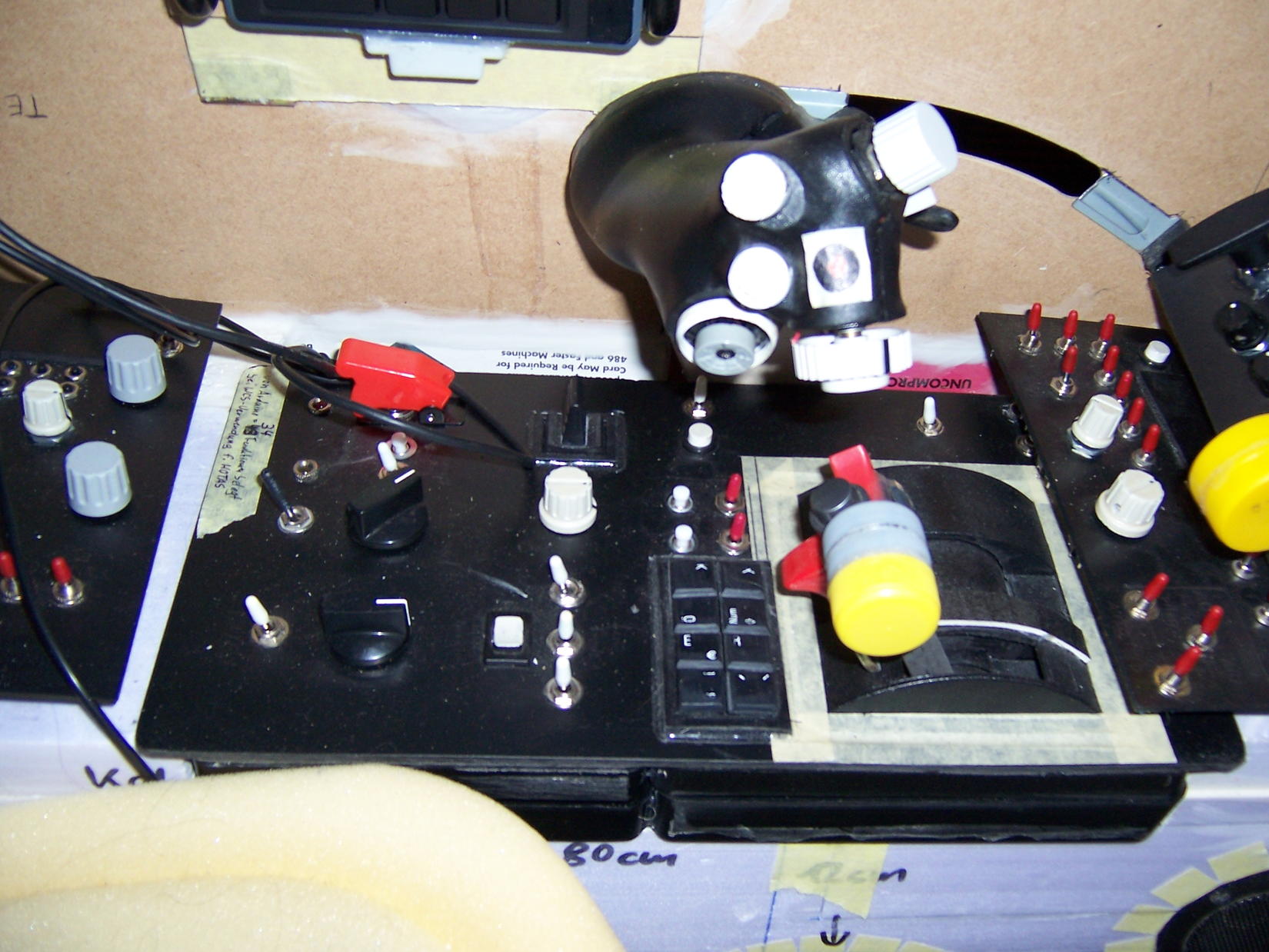
You are right it is taking longer to get the other stuff done than the main wiring so far but I have now moved the X-figher's Handle Button Rings to the Base and also moved the Download Button from the FLCS Base to the X-Fighter Base with an added LED to indicate on/off ...not sure why TM never did it? now I know how easy it was to do. Cutting the new 12mm x19mm hole for it in the Base was pretty easy, I drilled each corner with a small bit and then just "joined the Dots" with a Hobby/Exacto/Olfa Type Knife , the Plastic (ABS?) is softer than I thought , seems softer than the TQS plastic actually.
![[Linked Image]](http://simhq.com/forum/files/usergals/2017/01/full-40431-131182-xf_base_btns__1.jpg)
![[Linked Image]](http://simhq.com/forum/files/usergals/2017/01/full-40431-131183-xf_base_btns__2.jpg)
![[Linked Image]](http://simhq.com/forum/files/usergals/2017/01/full-40431-131184-xf_base_2.jpg)
![[Linked Image]](http://simhq.com/forum/files/usergals/2017/01/full-40431-131185-xf_base_4.jpg)
As you can see in the Pic above I use a Proline White Paint Marker I got at an Automotive/Welding Supply House (Welders use them) to label and mark orientation of the Black Plastic Parts so I can reassemble easily.
KB.
Posted By: Viper1970
Re: F16-FLCS + TQS (Original) USB Conversion - 01/09/17 08:03 PM
Hello Kbird,
wow you have the digital chips of Bob Church! Never was able to get some here in Germany those days, also none of the Thrustmasters I bought over Ebay had some in.
As far as I know, if you use the digital chips, you don't use the PS/2 plug anymore, cause all is programmed via the Gameport, is this right? That's why I never have tried to get the digital chips for my project, cause it isn't possible to get the digital gameport running since win xp.
For my MFD's I have another real antic gear. Mine are the old Quickshot Masterpilots I also had lying around for years, I modified a bit. The Thrustmaster ones are much better, cause they have 20 buttons around the "MFD". Mine have 24 buttons (6 in every row) which is incompatible with most aircraft. That's why my display is not exact in the center. I use one button in every row for other functions and I will leave them black, while the 20 which controls the MFD get white.
Hey, if you are able to fly CAP2, please make a quick report about the feeling of the flight model. I'm also much interested in flying it, but I'm far away of my first flight. Have bought it two months ago in early access state on steam, but on my laptop there is no chance to get it running.
P.S: For what do you need the "Download-Button" on your FLCS? It's connected to the Arduino board now, or am I wrong? The grips PCB is only the shift register board, you could use with an Arduino and a matching software, too. I don't think you need the "Download-Button" at all. Maybe I'm wrong, but it doesn't make sense to me. Or is there a way to download a joystick programming software to the Leonardo board itself (without running the software under windows in the background)? I only have Mega's here, which have to run a software (eg. Mobiflight) in the background. You also have to flash them with the right firmware before you could use them with Mobiflight, but only for one time.
Posted By: Sokol1
Re: F16-FLCS + TQS (Original) USB Conversion - 01/09/17 10:42 PM
The only possible use for this "donwload-button" for Arduino is for their reset function - for update firmware.
Of course can be wired as conventional button too.
Posted By: Viper1970
Re: F16-FLCS + TQS (Original) USB Conversion - 01/09/17 10:48 PM
Ah o.k. Now it's clear!
Posted By: Kb1rd1
Re: F16-FLCS + TQS (Original) USB Conversion - 01/10/17 05:46 AM
Yes Sorry Viper, I did not make it clear I just moved it to use as a conventional button for something.
and since it is an on/off toggle button I added the LED so I would know if I left it ON.
Yes with Bob's Chips you didnt need the Keyboard cable at all but until last week I never cut it off
I just curled it up and ziptied it in front, in case I ever needed it for the USB Mod.... that would be a nope
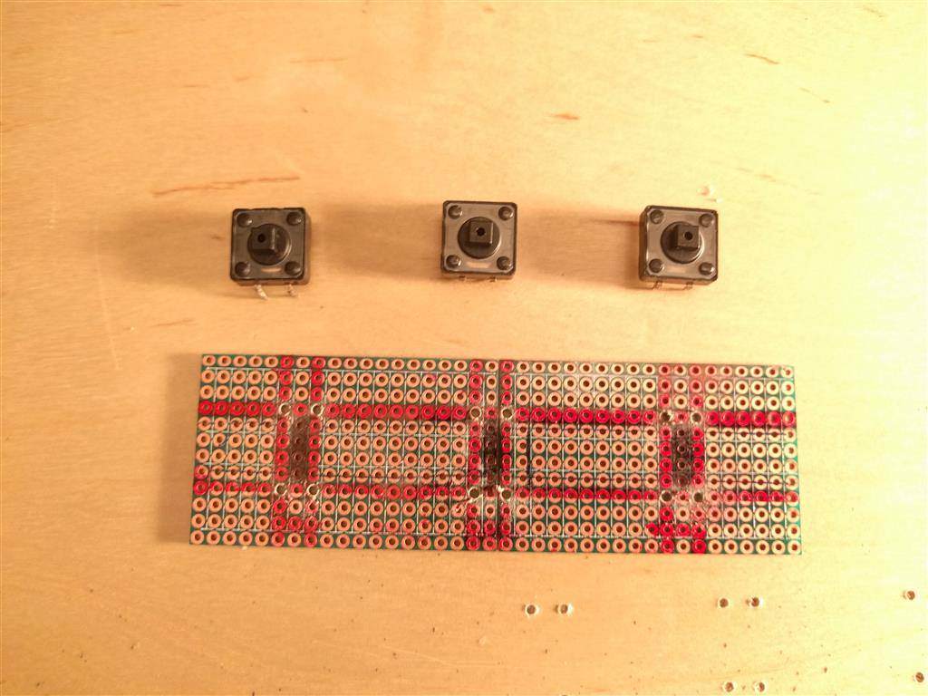
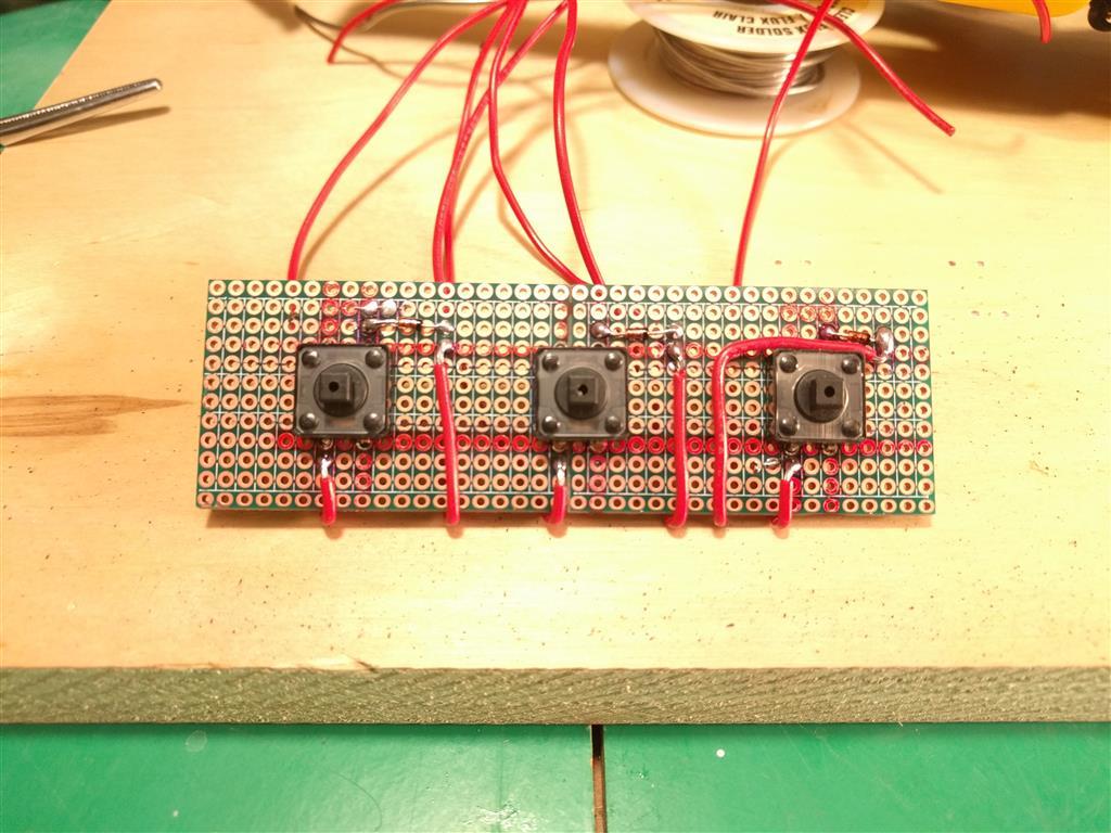
I got around to making the 3 Button PCB for the old X-Fighter Handle buttons last night,basically just a 1x3 button matrix
so I could practice how they are done,I used Diodes just to be sure, but it really didn't need to be a matrix AFAIK though.
Now I just need to figure out how to mount it , so the Board it held 3/16" off the Base under the push buttons. I may just mount it on Standoffs,like a Motherboard and just drill a couple more holes in the PCB (Protoboard)and Drill through the Top for the bolts.
They are rather large Tac switches but since they never got much use previously I thought it worthwhile re-using them,
since they were rated for joystick use originally , unlike these 10 switches for 10cent ones I see in every Arduino Kit.
KB
Posted By: Kb1rd1
Re: F16-FLCS + TQS (Original) USB Conversion - 01/13/17 05:49 AM
Been busy this week so not much progress on the Build/Conversion but
Solder Monkey has been kind enough to give me a list of the
Buttons,Encoders,Knobs,ProMicros etc He likes to use in his Builds/Conversion .... Much appreciated S.M.
Blue Headers are Clickable links.......... or were when this Post was made in 2017
Buttons, Knobs, Encoders, ProMicros etcEncodersOh - and after some playing,
don't use rectifier diodes on encoders. Use the 1n148 type. The rectifiers sometimes cancel out the signals in their activation period. 1n148s have a 6 nanosecond period - so you don't loose the pulse.
Knobs Switches ProtoBoard For DIY Circuit Boards Reset ButtonsSo you can reset the Arduino without opening the case for reprogramming.
Promicro Arduino Boards Get these if you think you lack room in the Base of your Joystick instead of the Leonardo Boards , these are likely Cheaper too.
*** Note if you are Using MMJoy2 you need the 5V/16mhz version not the 3.3v version if still available
***
Note2 SolderMonkey has Updated me on the ProMicro's and suggests getting this one instead as the 1st link has changed their Design
ProMicro 2 Simple Toggle Switches Switch Safety Covers 15/32 = 11.9 mm or right about 12mm.
Toggles TLE5010 Pot Replacements I use cheap microUSB phone cables 1m or 3 feet from bargaincableusa on ebay for all my mods to splice into the pro micro.
For my gear and the stuff for my friend with the flcs/tqs conversion. I still need to spec out some 3d printed mounts and figure out how to emplace them. His idea of using the wipers from the old pots is great, but it leaves you mounting questions on things like the f-22 pro. Easily solved. Thinking I'm going to end up drilling through the metal mounting flange, tapping it and mounting the board to the flange using the included standoffs. If MegaMozg keeps going the way he has been, we'll probably see tle5014 support or something as the 10/11 series boards die out. If the AliExpress boards stay in production, no reason for him to recreate the wheel for magres axis sensors.
For
Base Weights - steel, lead, tungsten in that order. Pennies are zinc - pretty light because of the density. For steel pieces, used weights from "play it again sports" and similar used sporting gear places are great. If you cut the ends off, you have a relatively easy to fit cylinder that fits in the edges of a base. For lead, offer to sweep the floors at a tire center for a few days, provided you keep the lead. Casting lead can be done with a blowtorch or large propane burner. Tungsten, I like the tungsten BB shot from online hunting supply but it's really expensive. I usually use steel and lead. Tungsten is dangerous, more so than lead. Don't try to mill it yourself or use power tools on it.
--S.M.
.
Posted By: Kb1rd1
Re: F16-FLCS + TQS (Original) USB Conversion - 01/17/17 09:48 PM
Had some time on the Weekend , so I now have a functioning FLCS in MMJoy2 , I still need to pack all the Wires and the Leonardo into the Base but everything is working as it should , though one old X-Fighter Pot is spiky so I'll change it for a FLCS one from it's old Base.
Also the Trigger is seen as one button at both 1st stage (guns) and 2nd stage (missle) , not sure if it is my MMJoy2 setup or the wiring at this point though. (Pics below)
Modding the FLCS grip and X-Fighter Gimbal was not to differcult as the screw holes are located in the same positions , I just filed ever so slightly the top of the screw posts to allow the stick to pull fully closed as the X-Fighter Gimbal Shaft has a triangular piece on it which is a bit thicker than the FLCS mount. The Gimbal shaft was also shorten slightly to miss the FLCS Pinky Button , and in the FLCS handle itself I had to carefully file a square slot for the X-Fighter shaft to lock into that the FLCS doesn't have. (see pics below)
***Note the plastics in both Handles are fairly Soft, so a simple metal file and small hacksaw was all it took to get the two peices to mate nicely.


KB.
.
Posted By: Kb1rd1
Re: F16-FLCS + TQS (Original) USB Conversion - 01/17/17 09:50 PM
The FLCS Trigger .... it appears I modded or fixed it in the past? , there are several bits of what appears to be part of a plastic container inserted ( margarine anyone ?
) not the original parts...not sure what was there originally though, so pls post a pic or two if you have them of the FLCS Trigger. I'm not not sure if that is why I am seeing the trigger as button 15 in MMJoy2 at both stages or not as yet....
KB.


Posted By: Kb1rd1
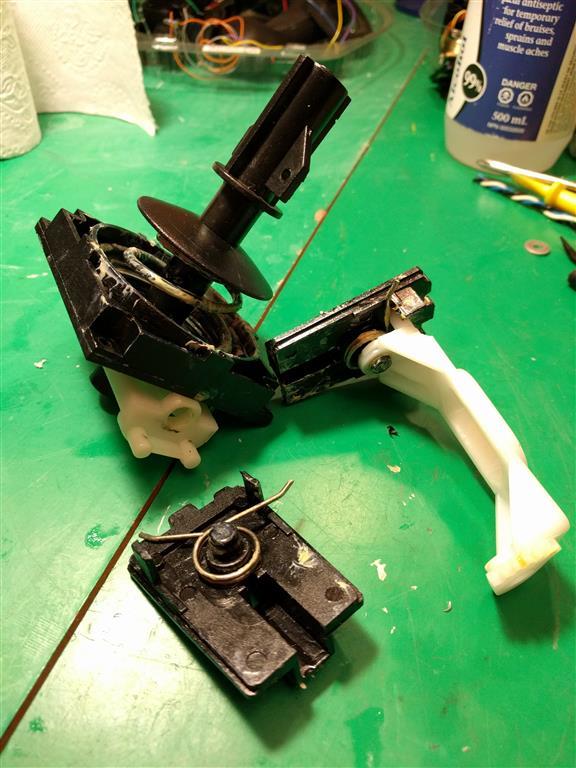
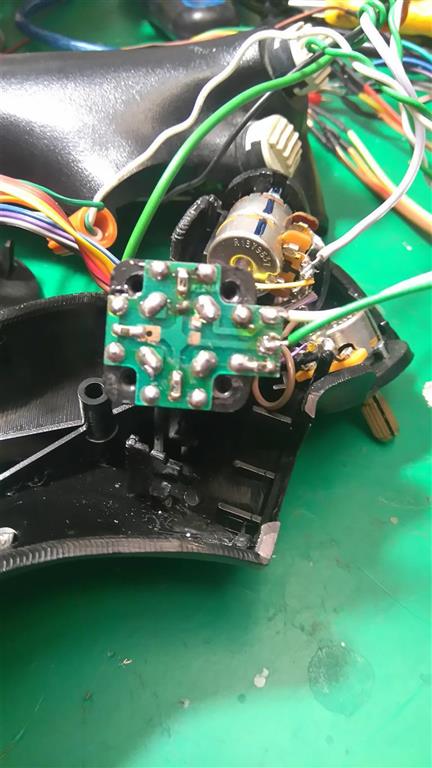
Re: F16-FLCS + TQS (Original) USB Conversion - 01/17/17 11:35 PM
TQS ConversionI have started on the TQS too, still need to add the 1N4148 Diodes to each wire in the Handle, but I decided to use the Hat Switch from the X-Fighter instead of a FLCS Hat Switch I have, as it is larger and easier to use. It also has a square base so I was able to make it fit into the Old Eraser Nub Box Holder within the Handle with only slight modification.
***Note/Forewarning..... the original soldering/wires are pretty fragile in the Handle of the TQS, so it was lucky I had taken lots of pics just after opening it as I have now found 3 wires hanging loose and I didn't know where they went to until looking back at my (enlarged) photos and resoldering them.
However I am not familiar with the way the X-Fighter Hat switch is wired with the Cross and SMD Diodes? resistors? and the Blue Resistor/diode on one of the wires, it only has two wires unlike a FLCS Hat switch (5 wires) so I am hoping MMJoy2 will see it once I figure out how to wire it, but it may need totally rewiring ?.


Posted By: Sokol1
Re: F16-FLCS + TQS (Original) USB Conversion - 01/18/17 01:18 AM
The X-Figthter use resitors because this HAT is connected in one axis - due gameport limitation.
So the axis is divided by resitors in several bands, each one correspond to one direction.
For use in MMjoy2 you dont need this, remove that resistors and use diodes. Probable will be more easy remove this entire PCB.
Posted By: SolderMonkey
Re: F16-FLCS + TQS (Original) USB Conversion - 01/18/17 05:33 AM
KBird - I took the liberty of hacking your image up. No... I am not an artist
Removing the PCB is a lot of solder to remove, so I left it in place.
Remove all four of those SMD resistors and the through hole resistor on the other side of the PCB.
Remove the old wires.
Now you've got a nice PCB with four switches in a cross.
Diodes and column wires to the outside contacts of the switches.
Wire all the inner contacts and run a wire from the inner loop back to your board as row.
You only need to connect all 4 pads, you don't need the fourth side of the loop.

Posted By: Kb1rd1
Re: F16-FLCS + TQS (Original) USB Conversion - 01/18/17 06:40 AM
Thanks for the Information Guys , and I really appreciate the "Hacked" Image SolderMonkey that makes it so much easier.
Use 1N4148 Diodes I assume ? since this is basically a 1x4 Button matrix correct ? so I set it up the same way as I did the 3 buttons on the FLCS Base.
Now I look more at the Image my understanding of where to put the Diodes seems backwards , I thought the Diodes went on the Row wire with the stripe toward the Controller Board ? ...funnily I'm looking at my schematic for the 3 button Board I made ,I have them on the Columns (but I wrote Row), That Board is working so I guess my understanding of the Wiki Page was wrong.... and I got lucky when I made the 3 Button Board
Not being into electronics the Fritzing images in the Wiki really didn't make much sense to me though....
https://github.com/MMjoy/mmjoy_en/wiki/Connecting-basic-inputs-and-setting-up-software#button-matrixKB.
Posted By: SolderMonkey
Re: F16-FLCS + TQS (Original) USB Conversion - 01/20/17 08:19 PM
Diodes block flow in one direction and allow it in the other. The diode doesn't care if its at the switch, the wire or the arduino. What matters is the direction of flow. Slide the diode across the switch in your mind. You have 1 row loop and four switches with individual wires. The diodes and their directional control have to fit in somewhere, so they get moved to the other side of the switches to the col wires.
Posted By: Kb1rd1
Re: F16-FLCS + TQS (Original) USB Conversion - 01/20/17 09:12 PM
Actually that's what I thought ie one direction of flow but when i did a test with a tac switch it worked in MMjoy even with the diode reversed so that just confused me more , so I was actually just online looking at button Matrix webpages to try and understand it a bit better, and if I have it right the Diode should be on the Column wire with the Diode Stripe (black) pointing back up wire to Switch, this page helped me being a non-electronics type...
Button Matrix Ghosting https://deskthority.net/wiki/Rollover,_blocking_and_ghosting
I realise now the X-Fighter Hat switch is actually 4 tac switches inside a box with a t-shaped "stick" to actuate them , which was leading to more confusion till I open it and realised what your wiring scheme was doing...


KB
Posted By: Viper1970
Re: F16-FLCS + TQS (Original) USB Conversion - 01/20/17 11:43 PM
Hi Kbird,
between the triggers second stage micro switch and the trigger itself, there is a piece of very stiff foam material. Don't know how it is spelled in english! It's something between rubber and a foam material.
Place it, where your plastic pieces are.
The functions is, that if you press the trigger, the spring presses the first stage and while you press further against this spring, you reach the second stage with the foam material, which activates the trigger stage two.
Have done a lot of working on my pit the last weeks. Finished the overhead, the yoke and the four lever throttle. Now I'm at the F/A-18 throttle which is nearly finished too. Have also integrated all panels in the pit. Next stations are the F-14 throttle, the F-14, F/A-18, AV-8B, AH-1F and AH-1Z grips. If this is done I have to wait for better weather, to sand and paint all the parts.
We never had so much snow the last years and never for such a long period of time. Hope this will finish soon
.
Posted By: Kb1rd1
Re: F16-FLCS + TQS (Original) USB Conversion - 01/20/17 11:56 PM
Hi Kbird,
between the triggers second stage micro switch and the trigger itself, there is a piece of very stiff foam material. Don't know how it is spelled in english! It's something between rubber and a foam material.
Place it, where your plastic pieces are.
The functions is, that if you press the trigger, the spring presses the first stage and while you press further against this spring, you reach the second stage with the foam material, which activates the trigger stage two.
The "foam" piece was missing or worn out so I replaced it as you see above with some some plastic pieces and both stages are now working but I cannot program the second stage it seems in MMjoy to act as two buttons pressed together, I posted on the MMjoy thread too for advice , so I am still hopeful.
Thanks.
KB
Posted By: Viper1970
Re: F16-FLCS + TQS (Original) USB Conversion - 01/21/17 12:06 AM
I think you have to seperate the two buttons using diodes, so that the circuit is independent, cause you press two buttons together if you use this originally two stage trigger. If the first button is pressed, the second will be ignored as long as the first still remains pressed.
Simply test it if they work without the mechanic and each one seperate. If so, you could use diodes. With diodes it must run, cause this is the same problem, you have if you use toggle switches. Leo Bodnar has a shematic of a matrix on his web page. But I have seen that you already used diodes in your project, just use them for the trigger too.
Posted By: Kb1rd1
Re: F16-FLCS + TQS (Original) USB Conversion - 01/21/17 12:17 AM
I think you have to seperate the two buttons using diodes, so that the circuit is independent, cause you press two buttons together if you use this originally two stage trigger. If the first button is pressed, the second will be ignored as long as the first still remains pressed.
Simply test it if they work without the mechanic and each one seperate. If so, you could use diodes.
Okay , good thought , but they go back through the Shift Register board in the Original FLCS Handle , so I dont think I can add a Diode ,but perhaps they could be rewired if needed with new wires ?, but it maybe more trouble than it is worth really , perhaps I will just have Guns on the trigger and put Missles on other Button instead eg S1 or S2.
KB
Posted By: Viper1970
Re: F16-FLCS + TQS (Original) USB Conversion - 01/21/17 12:45 AM
Found the schematic on my HD, have used it for my pit project too, cause I also had this column and row understanding problem
: (It's simple and clear to understand)

Posted By: Viper1970
Re: F16-FLCS + TQS (Original) USB Conversion - 01/21/17 12:53 AM
Ah,that's some other thing. Don't know how Thrustmaster originally made the logic for the grip pcb (shift register). Maybe they have used a seperate methode for the two stage trigger, cause you could also change them between simple joystick button and keyboard emulation.
Don't know how Mjoy uses the Thrustmaster shift register. Never have made anything with Mjoy.
The shift register itself acts like a matrix with diodes, so using extra diodes didn't make much sense. Wait for the Mjoy forum. They will have a solution I think.
Posted By: Viper1970
Re: F16-FLCS + TQS (Original) USB Conversion - 01/21/17 01:52 AM
Already gone to bed and while thinking of your problem, something came to my mind.
The two stage trigger always acts like two simultaneously pressed buttons. In real fighter jets you have the gun cam on one stage also. Or you could use it for a laser designator on stage one before you fire your weapon with stage two etc.
That's why they are always pressed together if you are at stage two. Only the first stage TG1 is stand alone. If you press completely down, TG1 and TG2 are both activated. That's the reason for this mechanic.
And for the missles it also more realistic to use a seperate button (I use S2 for example), the trigger is for the guns only in most of the fighter jets (not all, but most).
Posted By: Sokol1
Re: F16-FLCS + TQS (Original) USB Conversion - 01/21/17 02:22 AM
Don't know how Thrustmaster originally made the logic for the grip pcb (shift register). Maybe they have used a seperate methode for the two stage trigger, cause you could also change them between simple joystick button and keyboard emulation.
No, "two stage trigger" don't use "special hardware", is just 2 individual micro swtich pressed be same lever (trigger), they are seen by Shift Register PCB (ande joystick firmware) as 2 separated buttons.
The 2 micro switchs (yellow) inside TM F22PRO grip (same arrange for Cougar, TMW).
 http://i67.tinypic.com/6r283o.jpg
BTW - In the picture above the screw over lower switch is user "mod", to make the trigger less "heavy", more suitable for WWII planes.
Don't know how Mjoy uses the Thrustmaster shift register. Never have made anything with Mjoy.
MMjoy2 handle Shift Register boards in the same way that Tm controllers, buttons press, protocol serial signal for the controller.
Posted By: Kb1rd1
Re: F16-FLCS + TQS (Original) USB Conversion - 01/21/17 03:17 AM
Already gone to bed and while thinking of your problem, something came to my mind.
The two stage trigger always acts like two simultaneously pressed buttons. In real fighter jets you have the gun cam on one stage also. Or you could use it for a laser designator on stage one before you fire your weapon with stage two etc.
That's why they are always pressed together if you are at stage two. Only the first stage TG1 is stand alone. If you press completely down, TG1 and TG2 are both activated. That's the reason for this mechanic.
And for the missles it also more realistic to use a seperate button (I use S2 for example), the trigger is for the guns only in most of the fighter jets (not all, but most).
Yes I was thinking I would use S2 as the Missle Button too, Sokol's Pics are what I have , except In the 1st pic I don't see a PCB with S.Reg. , it appears the Handle was totally rewired....I don't have the F22 so maybe that was how it is. I think I saw a Trigger Mod somewhere during all this googling , perhaps at Cougar World? I will need to look further into it.
CW Trigger Fix ** there is one at Cougar World but not the one I was thinking of , which looked similar to Sokol's 2nd Pic (linked above)
KB
Posted By: Sokol1
Re: F16-FLCS + TQS (Original) USB Conversion - 01/21/17 12:08 PM
Yes I was thinking I would use S2 as the Missle Button too, Sokol's Pics are what I have , except In the 1st pic I don't see a PCB with S.Reg. , it appears the Handle was totally rewired....
Yep, that grip was rewired using diode matrix instead the Shift Register.
BTW - This mod you link is just a "feel" mod - add a extra spring for weight - don't change electronics.
Posted By: undefined
Re: F16-FLCS + TQS (Original) USB Conversion - 01/22/17 09:33 AM
.
Posted By: Viper1970
Re: F16-FLCS + TQS (Original) USB Conversion - 01/22/17 08:21 PM
Hello Kbird,
I have the F22, but haven't opened its grip until now. I think it has the same shift register as the FLCS. Only thing I've seen, is that the main pcb in the base are different between the F22 and the FLCS. The FLCS has the one which looks like a set square, while the one of the F22 is more like the one which is used in the Cougar (shaped like a simple square).
The picture Sokol showed, is the same principle as my grips are wired, except the go to the original Thrustmaster base pcb thru a 25pin parallel connector instead of a Plasma board, which sits in my cockpit and not in the sticks base anymore. I go this way to make my grips in the pit interchangeable. First I wanted to use a shift register for each handle, but due to some pros for my hardware setting and some other reasons ( only have a limited number of shift registers, but want to be able to built more handles in future) I decided to do it this way. Only drawback is the huge number of cables you have to solder to the connectors.
Posted By: Kb1rd1
Re: F16-FLCS + TQS (Original) USB Conversion - 01/23/17 01:41 AM
Yes I was thinking I would use S2 as the Missle Button too, Sokol's Pics are what I have , except In the 1st pic I don't see a PCB with S.Reg. , it appears the Handle was totally rewired....
Yep, that grip was rewired using diode matrix instead the Shift Register.
BTW - This mod you link is just a "feel" mod - add a extra spring for weight - don't change electronics.
thx,
Yes you are right, I could not find the Mod of the F22 Trigger that someone changed with a leaf Spring,epoxy putty and a small screw again....
I'll post back here if I do...
KB
Posted By: Kb1rd1
Re: F16-FLCS + TQS (Original) USB Conversion - 01/23/17 02:44 AM
Found the schematic on my HD, have used it for my pit project too, cause I also had this column and row understanding problem
: (It's simple and clear to understand)
I thought I had seen that Image before , and I had saved it but forgot about it, but the one I have (below) makes me now think even though my TQS Buttons are now (mostly) all working in MMjoy2 that the diodes are the wrong way around. In the image below, the diodes are on the Row wires with the stripes towards the wires (Arduino Board) not the switch....or is that the same as having them on the Column wires with the stripe towards the switch ? (which is what I have I believe)
 Button Matrixes
 are making me think I have a couple of diodes on my Cranial Implant facing the wrong way too
stuff ain't getting in
It didn't help that I didn't notice that there is (was) a small bare wire soldered between the two posts on the ANT Knob on the PWR side of the Pot so nothing was working at 1st as I had shorted the switches when adding the Pot's +5v wire, when I attached the Green Wire from the old Eraser Nub as my Pot PWR as SolderMonkey had instructed earlier. (Blue Wire in Ribbon is Pot GND/COM) Once I cut that link and put the ANT switch (T6) on it's own wire to the Arduino, things started to work as I expected.
I can't however work out/understand how MMJoy2 is setup to Input the Button Matrix fully, I never used MMjoy or MegaMozg's earlier Firmwares, perhaps I should google those tutorials? That section of MMJoy2 only shows (2) 10 input lines even though it supports 132 buttons. I had thought perhaps you program one Row at a time and send it to the Leonardo but that didn't work.
I have more buttons than I can put on one Row , so far I have B3 Row (+8 switches) and the ANT switch at B1 Row Setup but I still have the
X-Fighter Hat switch I installed to replace the Eraser Nub to setup on B2 . I am using the ICSP header Pins for Rows (COM) as I need the AXIS Pins F0,F1,F4 for the CH PEDALS as well (F7,F6,F5 are used by the TQS Z axis and RNG + ANT Pots) and the other side is Full except Pin 12 which I saved in case I can do a TLE5010 Mod, if needed/possible in the future.
KB
***Edit: See page 10 for more info and the fix 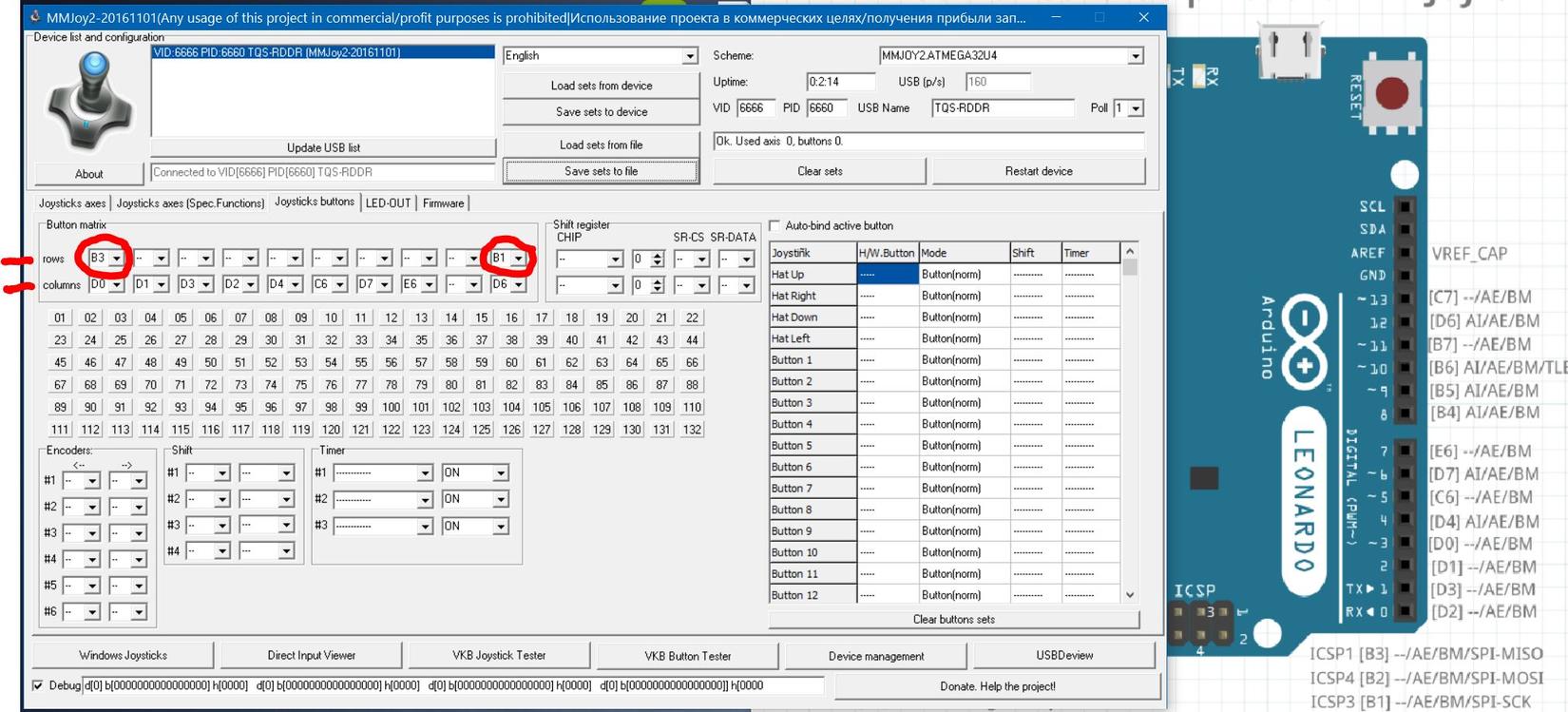
KB
Posted By: Kb1rd1
Re: F16-FLCS + TQS (Original) USB Conversion - 01/23/17 02:57 AM
Hello Kbird,
I have the F22, but haven't opened its grip until now. I think it has the same shift register as the FLCS. Only thing I've seen, is that the main pcb in the base are different between the F22 and the FLCS. The FLCS has the one which looks like a set square, while the one of the F22 is more like the one which is used in the Cougar (shaped like a simple square).
The picture Sokol showed, is the same principle as my grips are wired, except the go to the original Thrustmaster base pcb thru a 25pin parallel connector instead of a Plasma board, which sits in my cockpit and not in the sticks base anymore. I go this way to make my grips in the pit interchangeable. First I wanted to use a shift register for each handle, but due to some pros for my hardware setting and some other reasons ( only have a limited number of shift registers, but want to be able to built more handles in future) I decided to do it this way. Only drawback is the huge number of cables you have to solder to the connectors.
Thankfully the FLCS has Shift Registers so it was Easy ....no Button Matrixes or Diodes for me to worry about
, I think I know why some people didn't put Diodes in their TQS's
, I may have to stick to building Houses for a Living as my E.Eng. so far is lousy.... Lucky I don't have your Dream of a "Pit" and 8 different Controllers
, though I did just buy a FLCS+TQS for $50 today and he threw in a pair of CH Pro Pedals, a CH Pro Throttle and a joyswitch box and some cables for another $25... it was all I had on me , so a good deal I think especially since it was all in more than excellent condition , it looks like it was barely used , I'm not sure if the Pro Throttle even got out of it's Box it still has the twist ties on it , and none of the Manuals even look like they were Read.
Have to thank SolderMonkey for telling me to look on Ebay for 2nd hand Thrustmaster stuff

KB.
Posted By: Kb1rd1
Re: F16-FLCS + TQS (Original) USB Conversion - 01/23/17 03:00 AM
Sokol's Pics are what I have , except In the 1st pic I don't see a PCB with S.Reg.
Just a side note: the first pic that Sokol posted is of an F-16 FLCS grip; it was rewired (along with the TM TQS and the analog CH Pro Pedals) directly to a Beta Innovations PlasmaV2 controller board. The mess of wires is because the Plasma had more than enough button and analog inputs and also because it was my first such project
. I'm surprised that you managed to find the photos, it was so long ago - 10 years, at least.
Edit: I actually still have the PlasmaV2 board (the other hardware is long gone) - it was made in 2004.
I think Sokol1 has lots of images on his HD, as I see him posting in many of the Joystick Modding Forums and helping people out
Posted By: Sokol1
Re: F16-FLCS + TQS (Original) USB Conversion - 01/23/17 03:01 AM
You guys are using BU0836 Diode Matrix as reference for MMjoy2, not sure if is the same thing - can use different diodes orientation, look a CodeGoogle page.
That section of MMJoy2 only shows (2) 10 input lines even though it supports 132 buttons.
I think is not 132 buttons but 124:
100 buttons = 20 Rows x 10 Columns
+ 12 buttons for 6 Encoders (2 per Encoder)
+ 8 buttons for Shift
+ 4 buttons for Hat
124 buttons
Posted By: Kb1rd1
Re: F16-FLCS + TQS (Original) USB Conversion - 01/23/17 03:10 AM
You guys are using BU0836 Diode Matrix as reference for MMjoy2, not sure if is the same thing - can use different diodes orientation, look a CodeGoogle page.
That section of MMJoy2 only shows (2) 10 input lines even though it supports 132 buttons.
I think is not 132 buttons but 124:
100 buttons = 20 Rows x 10 Columns
+ 12 buttons for 6 Encoders (2 per Encoder)
+ 8 buttons for Shift
+ 4 buttons for Hat
124 buttons
Honestly not sure , I just see 132 buttons on the Button Tab ,(firmware 2016-11-01) I thought it supported a 10x10 Button matrix (100) plus the 32 Buttons Windows (DirectX) sees as Hardware Buttons.
It was just an Diode/Hat image I found online , but I did notice it was for the Bodnar BU Chip but I wasn't sure if it was the same setup for the Leonardo/ProMicro? it is what I thought you had posted for me before though , that the Diode should point to the Row Wire.
How in MMJoy do I program the Matrix , do you know a Tutorial for that?
Thanks...
KB.
Posted By: SolderMonkey
Re: F16-FLCS + TQS (Original) USB Conversion - 01/23/17 07:33 AM
Ok - switch matrices are pretty much all the same. If they work on the 386 board, they'll probably work in MMJOY.
Column wires. Row Wires. They intersect at a switch and diode. BUT the polarity of the diode has to be consistent throughout the matrix. All the bands point toward the row wires or all the bands point towards the column wires. Whatever you want to call them. in MMJoy you have the luxury of if you screw of the diode polarity, but the polarity remains consistent... you can just reverse the Row and Column selections in software and be good to go.
The diodes flow through the switch as if they are sliding along the wire to the other side of the switch.

Programming a matrix is just setting the Rows and Cols. To further disgrace your image...

This is a 4x2 matrix setup with 4 Columns and 2 Rows. The Row lines are separate in Gold and Gray. The Column lines are duplicates. They can join color to color anywhere - on the switch, on the control board or you can Y them along the way. As long as the diode is on the switches, and the band points the same way, in this case cathode band towards the row lines, the matrix can work. BUT if you screw up the polarity and can't see any switch action when you set it up, flip the rows and columns in MMJoy setup.
As per my usual disclaimer ... I am not an artist.
Posted By: Sokol1
Re: F16-FLCS + TQS (Original) USB Conversion - 01/23/17 12:19 PM
Honestly not sure , I just see 132 buttons on the Button Tab ,(firmware 2016-11-01) I thought it supported a 10x10 Button matrix (100) plus the 32 Buttons Windows (DirectX) sees as Hardware Buttons.
Looking at MMJoyJoySetup (01-11-2016) is listed 128 buttons + HAT, so is 132 buttons like you say.
Just don't see where connect all this.
BTW - The buttons that Windows see (up to 32) is dependent of Diode Matrix or Shift Register like the rest.
Mega_MOzg suggested Diode Matrix is similar to Bu0836 one - diode toward Rows (lines).

Posted By: Kb1rd1
Re: F16-FLCS + TQS (Original) USB Conversion - 01/23/17 06:44 PM
Editted by Kbird in Red+Bold, scroll this quote box if needed....Ok -
switch matrices are pretty much all the same. If they work on the 386 board, they'll probably work in MMJOY.
Column wires. Row Wires. They intersect at a switch and diode. BUT
the polarity of the diode has to be consistent throughout the matrix. All the bands point toward the row wires or all the bands point towards the
(switch) on the column wires.
(See Image) Whatever you want to call them. in MMJoy you have the luxury of if you screw of the diode polarity, but the polarity remains consistent... you can just reverse the Row and Column selections in software and be good to go.
The diodes flow through the switch as if they are sliding along the wire to the other side of the switch. Programming a matrix is just setting the Rows and Cols. To further disgrace your image...
This is a 4x2 matrix setup with 4 Columns and 2 Rows. The Row lines are separate in Gold and Gray. The Column lines are duplicates. They can join color to color anywhere - on the switch, on the control board or you can Y them along the way. As long as the diode is on the switches, and the band points the same way, in this case cathode band towards the row lines, the matrix can work.
( KB... even though the cathode (stripe) is on the column wire it is still "pointed to the Row wire (through switch) hence it is correct pointed at the switch) BUT if you screw up the polarity and can't see any switch action when you set it up, flip the rows and columns in MMJoy setup.
As per my usual disclaimer ... I am not an artist.
Future Readers Quote above edited for important points....scroll through it
Thanks Solder Monkey , your Images made my "LightBulb " go off
as I said earlier I am very "Visual", so I now "see" your explanation, (ie: slide the diode along the wire to the other side of the switch). Also If you didn't see the other post ,thanks for telling me to look on Ebay, I got a good deal I think this weekend on some Retro Sim Gear
...essentially a new FLCs+TQS ,CH ProPedals and Pro Throttle, for $75, they even came with the Manuals and Orig. Floppies
It looks like I got it right with physical testing, but nowhere in my reading the last few months did I see anyone mention the small bare connection wire on the ANT double Pot/switch . I knew I had a short or issue somewhere as none of the switches worked at 1st and some didnt have diodes (T6) so I knew that wasn't the issue, so I dismantled the TQS so I could get a better look at everything , it was then I noticed the small bare wire, as previously it was on the back side of the pot and 1/2 still in the handle, at 1st I thought it was a strand of solder and an accident, but the Soldering Iron didn't budge it, so I used my Clippers and the ANT T6 SWTH immediately started working so I knew I was on the right track.
What was once a TQS
(heat shrink not done yet as still testing)


THE OFFENDING WIRE ...as the other side of T6 Switch was also common to all switches

KB.
Posted By: Kb1rd1
Re: F16-FLCS + TQS (Original) USB Conversion - 01/23/17 07:24 PM
Honestly not sure , I just see 132 buttons on the Button Tab ,(firmware 2016-11-01) I thought it supported a 10x10 Button matrix (100) plus the 32 Buttons Windows (DirectX) sees as Hardware Buttons.
Looking at MMJoyJoySetup (01-11-2016) is listed 128 buttons + HAT, so is 132 buttons like you say.
Just don't see where connect all this.
BTW - The buttons that Windows see (up to 32) is dependent of Diode Matrix or Shift Register like the rest.
Mega_MOzg suggested Diode Matrix is similar to Bu0836 one - diode toward Rows (lines).
- Oh Wow , I maybe stuck if you don't know how to assign the Button Matrix in MMJoy2 being one of the Guru's around here
, I am trying to find old Mjoy or Mjoy16 Manuals as I now think that Mega-Mozg continued on the work from those projects, and it maybe why there is limited Documentation for MMJoy2.
- Mega Morg's Fritzing images didn't make sense to me at 1st as (in my case anyway) the ROW wires are Common wires to all switches so I didn't see how diodes could be on every switch and still on a common wire but I now realise the diode can be solder right to the switch and the common wire to the diode at each switch after looking at some sites about making your own Keyboard like at Deskthority , I founds these image there ....
Row diodes on homemade Keyboard

And the Columns done too...

KB.
Posted By: Kb1rd1
Re: F16-FLCS + TQS (Original) USB Conversion - 01/23/17 07:55 PM
So I found some old PDF's etc of MJoy16-C1 User�s Manual , and they include the wiring etc ( the pics/diagrams of wiring direct to a Mjoy16 Board show how with Arduino too) but MMJoy2 button Matrixes are programmed differently it appears...
Mjoy16_C1- PDF V1.1 From the Above incase it is no longer available..........
About use of diodes and their polarity All diodes shown in below sections are required to eliminate so-called �Phantom-Buttons� effect which occurs in matrix key layouts when three or more buttons are pressed simultaneously. They are already included on the Key Matrix board. If you are using the Key Matrix board then don�t bother reading this section.
The diodes shown are widely popular 1N4148 but may be any other type of low power fast switching diodes.
Since diodes are asymmetric devices it does matter which way you connect them. The black band shown on the diode in below illustration corresponds to polarity marking of 1N4148:

This band colour may be other colour depending on typical body colour of the diode. Other types may have different marking convention.
If you are not sure about the polarity of diodes you have you can easily test find this out by simple test described below:
1. Connect MJoy16 to PC via USB cable. Don�t connect any digital controls yet. Make sure that Windows has installed the MJoy16 and open Game Controllers panel for �MJ16�. This is done via Control Panel in Windows.
2. Take two wires Row A and Column 1 from MJoy16 digital inputs connector. When you connect these two wires together you should see Button 1 lighting up on �MJ16� panel.
3. Place the diode you have between these two wires in one or other way. When Button 1 lights up again make a note of the diode marking and remember this position as a reference.
4. When wiring all other controls use this reference to place all other diodes the same way.
Wiring digital controlsIf you don�t use Key Matrix board you will have to solder diodes directly to pushbuttons and switches. These diodes are necessary to avoid so-called �Phantom Buttons� presses. They should be soldered directly next to each button control. Below are some examples how pushbuttons and toggle switches are wired directly to MJoy16 board:
 Wiring pushbuttons
 If you don�t use Key Matrix board you will need to solder a diode in series to one of the pushbutton pins. A wiring example is shown below:
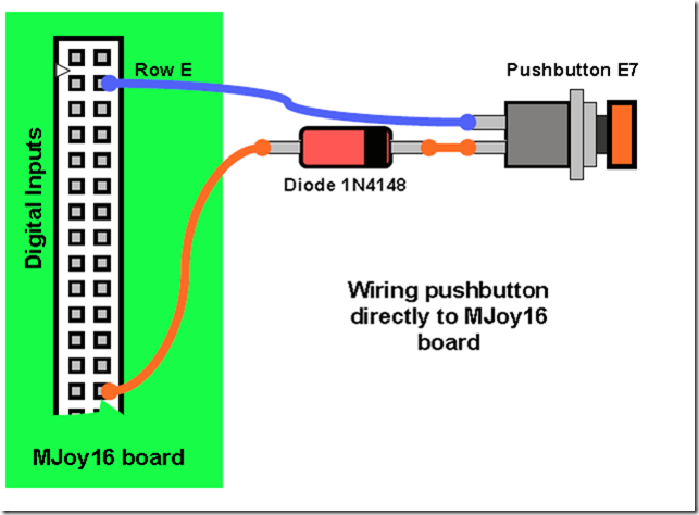 Wiring toggle switches
 Toggle switches can be single throw or double throw. MJoy16-C1 is mainly designed for single throw toggle switches but double throw toggles may also be used if required by your cockpit application.
Single throw toggle switches have two positions: �On� and �Off�. Single throw toggle switches are wired exactly as pushbuttons so please refer to pushbutton wiring description for wiring the single throw toggle switch.
Double throw toggle switches have three positions: �On1�, �Off� and �On2�. �Off� is the middle position. These toggle switches use 2 pairs of contacts on keys matrix. The principle of connecting them is that common pin is connected to Column signal wire and the other two pins are connected to different Row signal wires. Below is example of wiring double throw toggle switch without Key Matrix board:
 Wiring rotary switches
 Wiring of phase shifted rotary switches is similar to wiring of double throw toggle switches. The first thing is to find out which pin on the rotary switch is common. Its position depends on the type of rotary. On some rotary switches it may be in the middle but some may have it on one side.
Below is an example how to directly wire a rotary switch to the MJoy16 board:
 Wiring Hat switch
 Hat switch is 8-way hat switch and it is made of 4 microswitches arranged on 4 sides of hat switch enclosure. A small joystick handle presses one or two switches at a time depending on angle of deflection. When only one switch is pressed it gives four main directions at 90 degrees angles:
�UP�, �RIGHT�, �DOWN� and �LEFT�.
When two switches are pressed it gives intermediate directions: �UP-RIGHT�, �UP-LEFT�, �DOWN-RIGHT� and �DOWN-LEFT�.
Below is a diagram showing how to wire the hat switch directly to the MJoy16 board:

Posted By: Sokol1
Re: F16-FLCS + TQS (Original) USB Conversion - 01/23/17 09:19 PM
You are making a "keyboard"?
- Oh Wow , I maybe stuck if you don't know how to assign the Button Matrix in MMJoy2 being one of the Guru's around here
I am not "guru", just a "Google" - I know where are this or that related to "FrankenSticks".

This Diode Matrix thing is really confusing, practical for a dozen of button, but for 32.

Posted By: Kb1rd1
Re: F16-FLCS + TQS (Original) USB Conversion - 01/23/17 09:43 PM
You are making a "keyboard"?
- Oh Wow , I maybe stuck if you don't know how to assign the Button Matrix in MMJoy2 being one of the Guru's around here
I am not "guru", just a "Google" - I know where are this or that related to "FrankenSticks".
This Diode Matrix thing is really confusing, practical for a dozen of button, but for 32.
Well , you are the Guru of Frankensticks for sure
everywhere i go on the internet I find you have already been there and posted
Your Google-Fu is great Obi-Wan
I posted on the main thread too so I hope somebody knows as i think Mega-Mozg has disappeared ? or is still on holidays???
KB.
Posted By: Sokol1
Re: F16-FLCS + TQS (Original) USB Conversion - 01/23/17 10:08 PM
Now Mega_Mozg is involved with MoongosT-50 project.
Posted By: Kb1rd1
Re: F16-FLCS + TQS (Original) USB Conversion - 01/23/17 10:43 PM
Oh ok , he was answering question before Xmas but I haven't seen him since...
The T-50 looks very interesting , I was not aware of it
Virpil T-50 https://virpil.com/en/ I didn't know about the VKB Sticks either till last week, maybe i should of got one of them
VKB Controllers http://vkbcontrollers.com/?product_cat=vkb-controllers
Posted By: Kb1rd1
Re: F16-FLCS + TQS (Original) USB Conversion - 01/24/17 09:12 AM
I found this image by @Mega_Mozg_13 on page 6 of the Main Thread which shows he has a 6x6 matrix and 36 buttons seen in MMJoy2.
Looking at how he has designated the Rows and Columns must mean the Columns wires are also Common to each switch and be wired in groups of 6
(10 now for the 10x10 Matrix MMjoy2 now supports) so it looks like I need to group (make common) some of my column wires somehow.

KB.
Posted By: Sokol1
Re: F16-FLCS + TQS (Original) USB Conversion - 01/24/17 12:47 PM
Posted By: Kb1rd1
Re: F16-FLCS + TQS (Original) USB Conversion - 01/24/17 07:42 PM
Thanks Sokol , I am pretty sure that is what I have now , I can setup a 1x10 matrix and it works but as there are 14-15 buttons, I have 4-5 I cannot program in MMjoy2, so I need a 4x4 matrix of something similar so I can connect all 15 buttons to MMjoy2. Mega appears to have a 6x6 matrix in the image above , so I need to figure out how he wired it physically in the throttle since I may want to add more button later too.
KB.
Posted By: Viper1970
Re: F16-FLCS + TQS (Original) USB Conversion - 01/24/17 09:59 PM
Wow,
some real good drawings about the diode thing. Couldn't be a better time, cause I'm near my solder works for some of the throttles and grips I built.
Have built the F-14 throttle and as I had seen some more joystick and throttle stuff lying around, I thought why not building a V-22 Osprey throttle, too? I'm crazy I know, but I'm infected with the HOTAS-Virus.
I use the old pieces and put them together to get the shapes of the original thing. Not all is exact the same, but as near as possible, with exception of some extra features (original F-14 throttle has no ANT and RNG rotaries) I use. I try to make them as unremarkable as possible. Sometimes it succeeds and sometimes I'm not so happy with the result, but slowly I make improvements in the designs.
Will post some pictures with the real thing and my Frankensticks to see the difference between original and fake, if all stuff is ready
.
Posted By: Viper1970
Re: F16-FLCS + TQS (Original) USB Conversion - 01/24/17 10:20 PM
O.k.
here is the work of the last days. Left to right: F/A-18 like throttle, F-15/A-10 hybrid, F-14 throttle. They use all the same base and will also be interchangeable, like my grips. The only throttle with its own base is my F-16/AV-8B hybrid, cause of the design of the F-16 throttle grip.
All not painted yet and not sanded, some details are missing also (e.g. covers left and right on the rocker switch of F-14 throttle), but the main work is done.
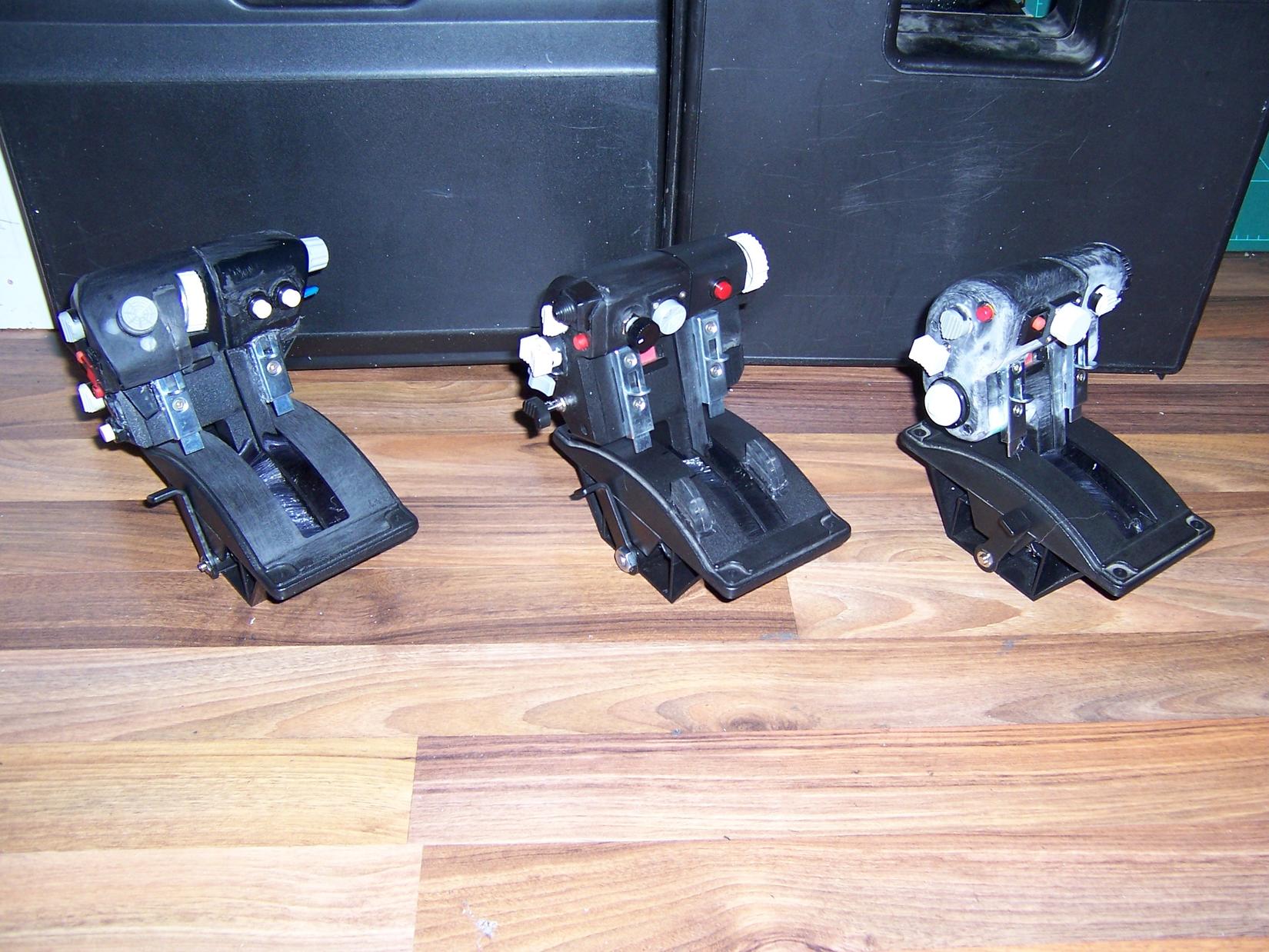
Posted By: Sokol1
Re: F16-FLCS + TQS (Original) USB Conversion - 01/24/17 10:42 PM
... but I'm infected with the HOTAS-Virus.
For sure.

Paint with "Paint Dip".
Posted By: Viper1970
Re: F16-FLCS + TQS (Original) USB Conversion - 01/24/17 10:55 PM
Ha you brought me an idea!
Anyone ever made anything with rubber coating spray? Is it abrasion-proof? Could be a solution to save some of the sanding works, which are really painfull. Have made two grips and worked for hours to get them finished.
You have to remove all the buttons again and I use sanding surface spray as base coat. But it's really a hard work. Maybe the rubber coating could save some time (O.k buttons have still to be removed, but the sanding has not be as excact
)?
Posted By: Kb1rd1
Re: F16-FLCS + TQS (Original) USB Conversion - 01/25/17 03:47 AM
Nice Viper 1970
, You really should Start a thread on your Pit Build I am sure Others will be interested and they would not find your Info and photos here on this thread easily.
Some plastics do not like Etching Primer (acid base) not sure about TM HOTAS's (ABS's?) but Rustoleum and Duplicolor (spellings?) make Plastic Primers , if it says sandable ,that usually means it has fillers and is a little heavier to fill micro imperfections etc.
Rubber coating spray they use for vehicles is for metal , used like a rock-guard on rocker panels, so I am not sure about it on Plastic either , an automotive paint store could maybe tell you since bumpers etc nowadays are made of plastic alot.
KB.
Posted By: Kb1rd1
Re: F16-FLCS + TQS (Original) USB Conversion - 01/25/17 04:30 AM
I found this image by @Mega_Mozg_13 on page 6 of the Main Thread which shows he has a 6x6 matrix and 36 buttons seen in MMJoy2.
Looking at how he has designated the Rows and Columns must mean the Columns wires are also Common to each switch and be wired in groups of 6
(10 now for the 10x10 Matrix MMjoy2 now supports) so it looks like I need to group (make common) some of my column wires somehow.
KB.
Okay I have figured it out I think, basically it is just my lack of Electronics background and my 1st time doing a Mod like this
My images of the homemade Keyboard soldering earlier in the thread and looking last night at the Image by Mega_Mozg of his MMJoy2 configuration with a 6x6 Matrix made me realise it was a Wiring issue in the TQS... NOT a MMjoy2 Configuration Issue. I then looked at the wiring scheme Sokol posted of the F22+TQS on a BU0386 Board closely (Blown up/zoomed) and could see how the Rows and Columns were physically wired, and noted that no Switch was on the same Column as any other Switch in it's "group" or Row. (insert lightbulb emoticon here) So I came up with my own 4x4 matrix wiring scheme which seems to work but I am not 100% sure admittedly that it is "electronically correct".
Note: I also had to move the Row off pin #13 (C7) to #11 (B7) as it would not stop blinking the yellow LED on the Leonardo with my wiring scheme, some research of the blinking issue revealed that pin 13 is traditional an Output Pin and best not used for this , I am guessing in a Button Matrix it is constantly polled as the matrix is scanned causing the LED to Flash?
Below is a scan of My Scheme Notes with the two blow ups of the Bodnar BU0386 Wiring scheme too. My scheme is not finished I need to add a Rotary (en)Coder (RC at top of scheme) and perhaps a few more Buttons to the TQS Base but so far it is only "proofed" on the Breadboard but it seems okay, I'm just wondering now if I have messed up the Diode direction or anything else? The Diodes are in the Column wires with the Stripe towards the switch BTW I did not draw that on the scheme however.
KB.


Had I looked at SolderMonkey's Pic of the Diode Alignment in the light of a "button matrix" instead of just at the Diodes,
I would of noticed he also indicated the Wiring for the proper Button Matrix hook up for this 4x2 Matrix too....
Thx S.M. 
Posted By: Sokol1
Re: F16-FLCS + TQS (Original) USB Conversion - 01/25/17 12:46 PM
I see (on Web) mouse painted with Plasti Dip.
I paint a modified Tm WCS.
Apply a protector liquid (forget name) to prepare the plastic surface, then conventional primmer, ordinary black paint, and latter apply a coat of gloss enamel.
Since no Plasti Dip in this "corneroftheworld", to achieve a textured surface the last paint cover is sprayed from distance, resulting in a "sand" surface.
That guy who used make left hand CH HOTAS in the past use Rust-Oleum paint to achieve a textured surface.
Posted By: Kb1rd1
Re: F16-FLCS + TQS (Original) USB Conversion - 01/25/17 06:07 PM
Posted By: Kb1rd1
Re: F16-FLCS + TQS (Original) USB Conversion - 01/26/17 12:35 AM
@Erichos was kind enough on the Main MMJoy2 thread to redo my TQS Wiring Scheme above for the electronically inclined, see this Post
Erichos's Post Below I have reposted the images and text for anyone following this thread in the future too... All Credits to ErichosHi Kbird, I only recommend you use version [20160818upd1] but as I said button matrix must work at any version.
I looked at your scheme, sorry but it is not very transparent :-) so I redrew it without changes and I hope it is clearer now, maybe :-)
Here is your scheme But Note the 1N4148 Diodes inline in the column wires facing the Switch are not shown: **Edit
 this image was also posted by Erichos
 Important thing is to set MMJoy2 correctly
 So connect your Arduino and click "Load sets from device". Then we start setting.
Step 1: set which pins you use for ROWS and COLUMNS
Step 2: click "Save sets to device" from now if you push any button you have to see red square with number 01-132 on the left side of MMJoy2 window (there is 01 in my picture because I pushed button connected between ROW1 and COL1 and press "PrintScreen" on keyboard)
Step 3: now you can set which H/W.Button will be displayed as button in Windows. Doesn`t matter if H/W.Button 01 will be Joystick button 05 or 25... It is up to you. But OS Windows knows only 32 buttons and 1 HAT so SUM=36 buttons.
Step 2: again send your settings to Arduino
Now you click on the left-down "Windows Joystics" and then "Properties" and must see this:

If you push the button 01 you have to see red square with number 01 on the left side of MMJoy2 window and red circle button 01 in joystick properties window.
That`s all :-) I hope you do it now.
Read more:
http://simhq.com/forum/ubbthreads.php/topics/4331393#ixzz4Wp6Yaka3 KB
Posted By: Viper1970
Re: F16-FLCS + TQS (Original) USB Conversion - 01/27/17 10:21 PM
Hello,
thanks for your references. Have decided not to use plastic dip, cause it's made for easy remove also. Not a good solution for a grip you have in your hands for hours. Think the coat will not stay long on the handle.
So I will do it my old way with filler ( hours of sanding the fine shapes

) and simple car paint, black matt. After this the lettering has to be done and as finish I will take a matt clear paint, so that the lettering is fixed.
My homebase is "Fursty" (F�rstenfeldbruck) near Munich in Bavaria (Germany). Half an hour distance to the "Oktoberfest"
. You can get all materials here, but in Germany materials are often really expensive, specially in our building centers.
I will make a seperate thread soon, if more is ready for showing (painted). Have finished the body shell of my V-22A throttle today and begun with the F/A-18/AV-8B grip handle. My girlfriend screems "Who needs twenty stick and throttle for flightsimulation" so I decided to make an F/A-18/AV-8B combi stick with changeable Coolie and castle hat switches (only difference between the two). Have used small neodym magnets for this. One grip reduced, so only 19, no more need for crying
.
Joking apart, I ever wanted to have the right feeling of the bird you are flying. At first I only wanted to have one side stick controller and one center stick to be changeable. Then I heard of the new AV-8B in Falcon BMS 4.3 and of Combat Air Patrol 2. So the idea of a Harrier like control came to my mind.
As I have collected a lot of defect Suncom and Thrustmaster sticks and throttles from ebay the last years, I decided to use this stuff and make some more HOTAS for the major fighters and helicopters. They are not exact copies, cause I have to make some agreements in case of my budget and the things that are possible under this circumstances, but as close as I can do it with my possibilities.
I hope it gives a little bit more realism to the flying in my universal cockpit. If I had much, much more money, I had a seperate room with a cockpit for every single aircraft, but this will be a dream for the rest of my life.
Posted By: Kb1rd1
Re: F16-FLCS + TQS (Original) USB Conversion - 01/27/17 10:59 PM
Hello,
thanks for your references. Have decided not to use plastic dip, cause it's made for easy remove also. Not a good solution for a grip you have in your hands for hours. Think the coat will not stay long on the handle.
So I will do it my old way with filler ( hours of sanding the fine shapes
) and simple car paint, black matt. After this the lettering has to be done and as finish I will take a matt clear paint, so that the lettering is fixed.
My homebase is "Fursty" (F�rstenfeldbruck) near Munich in Bavaria (Germany). Half an hour distance to the "Oktoberfest"
. You can get all materials here, but in Germany materials are often really expensive, specially in our building centers.
Are you talking about AutoBody filler like Bondo? (acrylic 2 part filler) , it would work well but for finer work I like Auto Glazing Putty better for small scratches etc it is easier to smooth out and to sand out ,works great on MDF (FiberBoard) etc too
Bondo Glazing Putty
http://bondo.com/products/automotive/bod...2CbUUHtoYETh.97Bondo Filler
http://bondo.com/products/automotive/body-filler/bondo-filler-261.html#V2TbepciKhwUyK6R.97KB
Posted By: Viper1970
Re: F16-FLCS + TQS (Original) USB Conversion - 01/27/17 11:22 PM
It's a spay, but not a normal base coat. It's called " Spritzspachtel" here in Germany. I used it a lot in my time as car mechanic, as I refurbished oldtimers. It's "stronger than base coat and can fill many small scratches easy. You can use it at metall, but also at plastics ( never make to thick layers, cause they will easy crumble ).
We used it a lot at GFK (glass fibre) parts of "angry tuned" beetles, those days.
Posted By: Kb1rd1
Re: F16-FLCS + TQS (Original) USB Conversion - 01/28/17 12:24 AM
I didn't know the Harrier was in BMS too ...interesting ......are you saying I need to convert my second FLCS to a Harrier look alike
I am sure people would like to see the Pit Build and what you are doing too , not just the final "pretty" Hotas's in a nice Row
Well at least your Girlfriend is no# 20 not no# 21 on your list now , that will make things better
don't have that issue here...especially with a Dining table looking like this....

KB.
Posted By: Viper1970
Re: F16-FLCS + TQS (Original) USB Conversion - 01/28/17 12:46 AM
Haha,
this is what my floor looks like when I'm at my works. My whole living room is full with parts and the at rest there is my pit and some place for sleeping on my couch. Not a flat for a woman at the moment
. I can really understand her, hm a little bit. Only my kitchen and the bath is no workshop at the moment.
Will make some pics of the pit for a new thread, too. At the moment I use every single free minute for building, cause I want to finish the project this year. Slowly it begans to jangle a bit, to have no room for living
. And I have also to renovate my floor and the bathroom this year, so the pit must come to an end in a conceivable time. At least to a stage, where I have only some electronic works and the programming itself to do.
P.S: That's why those twenty HOTAS actually not such a good idea, for finishing the pit soon. But if I will make them at a later time, maybe I have to rebuilt some of the electronics, which is much more work then.
Yes Falcon BMS has a very detailed AV-8B in, since the release of 4.33. They have also a detailed Hornet now.
Posted By: Kb1rd1
Re: F16-FLCS + TQS (Original) USB Conversion - 01/28/17 06:19 PM
Oh my Floor Too
that was just the table , though with 20 Controllers and a Pit under Construction I think you might have me beaten
, hopefully I'll get some done this weekend as I was building a Bench Power Supply out of an old ATX Computer PS as well.
KB
Posted By: Viper1970
Re: F16-FLCS + TQS (Original) USB Conversion - 01/30/17 11:10 PM
Hi Kbird,
how is your project going on? Have completely finished my V-22 throttle (only body shell) and started the AH-1Z Viper/UH-1Y Venom Cyclic which I also finished today (it's mostly like the F-16 grip, only the buttons are different and some minor details) . Tomorrow I will go back to my AV-8B/F/A-18 Hybrid. Had some problems with it, so I decided to make some others, before I throw it at the wall
.
I have also started with the F-14 grip, but made the decision to build the F-14D version. It has more functions available as the B-model version. Maybe I will make a B-version too, but for this one you have to use a 4 way rotary for the weapon mode switch. This means there is always a contact closed. Don't know if the old thrustmaster electronics I still use, like a contact which is always closed, specially if you want to press other buttons also. Must test this before I make this one.
Now I'm at the end of my HOTAS orgy. If the weather will get a bit better the paintwork has to be done. Hope this will be next week.
With the throttle and sticks I've built, I could fly most of the planes I really like in a relatively realistic way, cause you could combine all sticks with all throttles or the collective. This way most aircraft controls can be simulated. Not all are 100% like the original, but close enough for my purpose.
Posted By: Kb1rd1
Re: F16-FLCS + TQS (Original) USB Conversion - 01/31/17 12:19 AM
Hi , I did a bunch of wiring and soldering over the weekend but did not get the TQS quite completed , it seems I was given Momentary switches that are always On (Closed) instead of Always Off (Open) so I need to remove them and replace them this week.
At 1st I thought I had an issue with my Button Matrix as MMjoy showed them always pushed , took a while and a bunch of de-wiring and checking the Matrix to figure out I had the wrong switches and it wasn't my Button Matrix after all.

I am definitely thinking Shift Registers are the way to go now
.
KB.
Posted By: Kb1rd1
Re: F16-FLCS + TQS (Original) USB Conversion - 01/31/17 12:59 AM
Since I was using the old TQS Cable and it has 10 wires and I only need 4 for USB, I decided to also (re)add a Headphone and Mic Port to the TQS Base, this is something I also used years ago too... Headphone cords are always too short it seems , and I like to Fly with Headphones ..it seems more immersive that Way.
I also put a Rotary Encoder (Bournes PEC 11) into the Back of the TQS Handle (Vertical part) so I can use it with my left pinky , it may not suit everyone but an accident a few years ago (nearly lost my hand) means only my Pinky has any Feeling and the Thumb only moves up and down , so I am still not sure how useful the TQS is as a Whole yet.
This Encoder :
PEC 11 Encoder , I got it locally though....
It just fits into the Handle into one of the Holes in the ABS Webs with a little web "adjustment", I enlarged the hole in the back to 10-12mm and pulled the wires back into the handle (still hidden) and then down to the TQS base. There is not a lot of room under the TQS Handle Vertical Cover for wires , just the Ribbon cable really , so I used an old Soldering Iron Tip to "cut" a Wiring notch/channel through the Webs for it's 5 wires and also some of the 5 Wires from the New X-Fighter Hat now mounted in place of the Eraser Nub. ( I used the old green wire from the Eraser Nub to Power (+5v) the RNG and ANT Pots btw.) The Encoder is Hot Glued into place as I discovered the Shaft threads etc were not quite long enough to put the Nut and Washer on once the Cover was in place, but it seems solid as it was a tight fit anyway.
KB


Posted By: Kb1rd1
Re: F16-FLCS + TQS (Original) USB Conversion - 01/31/17 01:03 AM
I was having Trouble getting the Encoder to Work in MMjoy , but Erichos to the Rescue again with his reply on the Main MMJoy2 thread here :
Encoder How To Link :KB
And Here: Thx Erichos... Erichos's TQS Rotary Encoder and MMjoy2 SetupHi Kbird, so make connection like this:
Open MMJoy2 and start setting:
Step 1: set Columns and Rows.
Step 2: Save sets to device.
Step 3: now turn the rotary encoder left/right to find out which H/W buttons are active (they are blinking RED).
In my example is Enc connected to buttons 1 and 2.
Step 4: set that button numbers that were blinking during turning Enc.
Step 5: set Timer, delay as you want, it`s up to you, 20ms is fast, 40ms is standard (for me).
Step 6: set this, I think it`s clear on the pic.
Step 7: Save sets to device.
AND FOR NOW you cannot see blinking H/W buttons on the left side during turning Enc. It is NOT mistake, it`s OK.
Step 8: click VKB button tester (or Windows Joysticks) and here you can see result of your work - blinking button 1 if you turn Enc to the left and button 2 if you turn Enc to the right (or vice-versa).
That`s all Kbird. I hope it is clear for you.
EDIT: I want to add some info about Delay setting, there is a difference between Timer ON+OFF and ON, you can test it. If you need only impulse generator, set 20ms and ON+OFF, that means the Enc generates single pulses with pulse length 20ms, it is useful for trim tabs, manual gear operating and so on...
But for operating compass or radio freq you can test setting Delay 120ms/ON and now if you turn Enc fast, it generates 1 long pulse so it is good for primary inaccurate setting and slow turn generates single pulses for precise setting. It is very handy for compass setting, radio freq setting and so on...
EDIT 2: MMJoy2 author mega_mozg_13 wrote at page 101:
firmware support special modes only for first 32 buttons and HAT.And of course an "Encoder" is considered "special mode" so you have to use only first 32 buttons for them. OK?


KB
Posted By: Viper1970
Re: F16-FLCS + TQS (Original) USB Conversion - 01/31/17 09:43 PM
Hi Kbird,
looks good!! I've also hot glued alot of my buttons and switches, cause at many points of my HOTAS the shaft threads are always to short for a normal attachment. Only drawback is, if a switch needs to be replaced you have to use some hot air to get the switch out and this must be done real carefully, cause of the plastics which are melting very fast. I use the hot air soldering gun of my reflow station for such actions. It has a very thin hot air tunnel and the temperature can be adjusted very precisely.
Posted By: Kb1rd1
Re: F16-FLCS + TQS (Original) USB Conversion - 02/16/17 08:33 PM
Just a short update , I have not disappeared
, my Order of TLE 5010 Board finally arrived and I have been having issues mounting them in the X-Fighter base , and I didn't like my 1st try in modify a FLCS Pot wot work with the magnets , so I'm having another go at that.
Still waiting for my order of some Pro Micro's to arrive , been over a month now , they are smaller than the Leonardo's I started with and should fit in the FLCS + TQS bases better , I had to remove the 2.1mm power connector off the FLCS Leonardo to squeeze it in and even then I am having to bend the Dupont pins etc to make it fit still.
I did add a Tac switch to bot the FLCS and TQS to enable me to reset the Arduino Boards should I need to load a new MMJoy2 firmware without having to open the bases to push the Arduino on-board reset buttons. I simply drilled a 1/16th (1.5mm?) hole in the base which I can insert a small Allen key or paperclip to push the button , that way it can't be set of accidentally ,though I am not sure it would be detrimental if it was set off accidentally.
KB.
Posted By: Viper1970
Re: F16-FLCS + TQS (Original) USB Conversion - 03/05/17 08:15 PM
Hi Kbird,
already at your project? It's been a while since I was here the last time. Sadly my landlady passed away last month and it's very likely that I have to leave my flat now, cause of home requirements of her son.
So my project is on hold now and maybe for the next two years. Have built most of my furnitures by myself and integrated it, to get the most space available in this little flat. This was the only possibility to make my homepit project possible. Now I have to start from scratch in a new flat.
Will make a seperate thread before I disintegrate the pit for the move and show the last state of it, with all the sticks and throttles I've built.
Cheers Viper
Posted By: Kb1rd1
Re: F16-FLCS + TQS (Original) USB Conversion - 03/06/17 04:29 AM
Hi Viper ,
Sorry to hear that , the last few times I have had to move it was for Family moving in too ,except the last time it was really so they could raise the rent more than they are allowed in one yr here , but there isnt much you can do about it , a year later and i still don't have my Damage Deposit Back either.
Why a 2 year wait though to continue your Pit ?
Actually I am still waiting for some Pro Micro's I ordered off AliExpress the same time as the TLE5010's which I've had for 3 weeks now, to replace the Leonardo's to get through Customs ,( I think) , it is real slow cos of the Fentanyl Drug coming in from China now , so they search with dogs and xray ALL incoming mail these days. So other than (unsucessfully so far) working out how to make a 1P12T rotary switch work with MMjoy I haven't been working much on the conversion unfortunately as I didnt want to assemble everything and then have to do it again when the ProMicro's got here but I am wondering if they have disappeared but you can't complain to the Seller till it is 60 days post shipping.
Posted By: Viper1970
Re: F16-FLCS + TQS (Original) USB Conversion - 03/13/17 02:31 PM
Hi Kbird,
it was a real problem to get a flat 4 years ago. I'm ill and have a disability pension, which isn't very high. That's also the reason I couldn't buy very expensive parts for my pit and have to make most of it by myself. Here in Germany it's very hard if not to say nearly impossible to get a flat with this shortcoming I have and as a single father with an 18 year old son the problem becomes much harder.
The flat I had was the flat of a acquaintance of my father. It was small, but I could do what I want and had the assurance to live there as long as I want. Now since she passed away things have totally changed, cause this the assurance was only made vocally. Nobody expected that she will pass away so soon. She was only 60 years old.
Now I have the problem to get a flat and after this I have the problem with my furnitures, which are all integrated in this flat. When I put them out of here most of them aren't usable anymore. The new flat has to be not more then 60qm, cause of my disability pension. And there is no way to integrate all the furniture again, cause I don't know the hirer. My pit is a real monster, and I don't want to rebuild it. It was hard enough to built all until now. I had to wait the last 20 years to get my dream come true and now it's over again. Don't know if there is a way to dispose the pit in the new flat. There are also much paintworks I have to do and I don't know the conditions of the new flat, apropos balcony and the other renters.
That and the fact that the whole thing until I get my cancellation will also take a while, makes me think, that the pit project is on stop now for the next two years. I hope I can continue at all. I had better done things a little smaller, but as I said it was always my dream for the past 20 years and never becomes reallity, cause of my job, my exwife and some other things in life. Now since I'm ill, I had the time for it, but very low money and not the best state of health for such a project. So things grow really slow and I had to arrange my flat before I had the place for my pit also. This all must be done once again. Don't know if I'm even able to make this all once again, but if I will do it, it will take a long time again.
Posted By: Kb1rd1
Re: F16-FLCS + TQS (Original) USB Conversion - 03/19/17 07:57 AM
HI Viper ,sorry been a few days since I checked in since my Conversion is at a standstill , I'm still waiting for the Pro Micros' from China still.
Sorry to hear about your Landlady , and how Her Family is treating you now , that's pretty tough , and I wish you the Best in your search for a new Home.... perhaps your Son will need to Rent a 2 Bedroom and you'll be his Room-mate instead
KB.
Posted By: Viper1970
Re: F16-FLCS + TQS (Original) USB Conversion - 04/18/17 02:21 PM
Hi Kbird,
I'm revived again
! Had to manage some things the last weeks, so I had not much time for my hobby. As it looks at the moment, I could stay another while in my flat. Hope it will be for the next year, so I could finish my project before a possibly move to another location.
Have seen your FLCS conversion with the X-Fighter base in the MMJoy2 thread. Looks nearly similar to my conversions. The X-Fighter has the much better base than the FLCS or the F22.
Most of my fighter and helo based controls are theoretically finished (solder work has still to be done). The circuit diagram for those controls is ready (hope its running in reality too

), but now I have to do the 4 lever throttle quadrant for the big birds.
I think I will try to use MMJoy2 for this one, cause I need 10 axis for the controls of this quadrant. 4 axis for the engines, 1 axis for the thrust-reverser, 2 axis for mixture and propeller, 3 axis for pitch, roll and yaw trimming. Have read a bit in the MMJoy2 "monster-thread" but I'm not really clear about some things, so I want to ask you, cause you use MMJoy2.
I have 3 arduino pro micros here. Is it possible to flash them with the MMJoy2 firmware, so that they look like a standard game controller to windows, or must the MMJoy2 software always run in the background to use the Pro Micro as a game controller? Is it possible to use one Pro Micro for all 10 axis (which appears as two separate game controllers in the win sys config) or must I use two pro micros for it (cause of the windows limitation to 8 axis per device) ?
Many thanks for your help!!!
Viper
Posted By: Sokol1
Re: F16-FLCS + TQS (Original) USB Conversion - 04/18/17 06:27 PM
MMJoy2 is a firmware for create a HID joystick controller using Arduino board that will use Windows native drivers - and don't rely in 3rd part drivers for install nor software running in background for work in games.
MMjoySetup software is used once after flash the firmware for customize this new "joystick" parameters, e.g. device name, VID/PID numbers, number of axis (up to 8) numbers of buttons (up to 128 - depends on Arduino board used available number of pins for input), buttons mode, encoder support (limited to 6) and axis response curve.
Once done this customization the new joystick is "PnP" for Windows.
Is it possible to use one Pro Micro for all 10 axis (which appears as two separate game controllers in the win sys config) or must I use two pro micros for it (cause of the windows limitation to 8 axis per device) ?
No, Mmjoy2 use Windows 8 axis limit (and number of axes depends Arduino board available pins, PRO Micro limit to 6) and don't allow combine 2 devices in one (probable due low memory space in ATMEGA32u4).
Posted By: Kb1rd1
Re: F16-FLCS + TQS (Original) USB Conversion - 04/18/17 06:29 PM
*** Beaten to it by Sokol1
Hi Viper , glad to hear you are sorting things out with the Flat , that is really good news.....
Yes MMjoy2 is in reality just a new Firmware for the ProMicro/Leonardo which you then upload "Sets" to with the MMjoy2 Program . Looking at the MMJoy2 Pin layouts (below)
it looks like there are 12 pins you can use for Axis's (any labelled with AI) and still have some pins for Buttons too from a single Pro Micro, but the windows limit will stop you at 8 axis's I think,
but I have not tried it , I use 6 axis's for my TQS + CH Pro Pedals (Pedals are connected via a gameport cable to the TQS which I added a gameport socket too) , so 6 is no issue.
*** edit.... I see Sokol says only 6 axis's though I am not sure why ???
The Pro Micro must be the 5V - 16mhz version though.....
Get the recommend (on the main thread) MMJoy2 18-8-2016 Firmware as the latest has a few bugs (V.11-18-2016) from here:
https://sites.google.com/site/mmjoyproject/fajly-dla-skacivania
![Attached picture Pins_Arduino[micro].png](/forum/ubbthreads.php/ubb/download/Number/1454/filename/Pins_Arduino[micro].png "Pins_Arduino[micro].png")
![Attached picture Pins_Arduino[leonardo].png](/forum/ubbthreads.php/ubb/download/Number/1455/filename/Pins_Arduino[leonardo].png "Pins_Arduino[leonardo].png")
Posted By: Viper1970
Re: F16-FLCS + TQS (Original) USB Conversion - 04/18/17 10:20 PM
Hello Kbird, hello Sokol,
I have managed to get MMJoy2 running on my Pro Micros. Really cool piece of software!!!
I have flashed two of my Pro Micros. Running each one with 5 axis and have given them 2 different VID/PID and names.
I don't use any buttons, just the axis. The buttons are programmed with a Arduino Mega and Mobiflight for the MSFS.
That way it is possible to program keyboard macros directly to the switches or use the FSUIPC directly.
The axis limit is no problem cause the MSFS has no problem with more than one controller at the same time.
I use this Throttle Quadrant only with the MSFS and not for other sims.
The cockpit is now completely primed and ready for the finish-paint. The backseat (workplace) is already painted and the electronics are running.
This place is used for normal computing, or as a WSO-pit and for other combat sims, like Dangerous Waters or SBPro PE 4.
It has a modified Attack Throttle with a FCS TopGun stick and a very small rudder system under the desk. Both are converted for USB. Have also
made a second special keyboard with shortcuts for all flight, tank and naval sims.
This keyboard has a few switches and a gear lever also, so you can play the WSO in sims which support it. I run it with HID-Macros and an
Arduino Mega with Jims Link2FS Keys for the switches and the lever.
Will make some photos soon.
Many thanks to you both for your help!!
Posted By: Sokol1
Re: F16-FLCS + TQS (Original) USB Conversion - 04/18/17 10:20 PM
*** edit.... I see Sokol says only 6 axis's though I am not sure why ???
I am saying that for Arduino PRO Micro if want use 32 buttons + HAT will remain pins for 6 axes,
but can use 8 if instead use Arduino internal ADC use external via their serial connection, or use Shift Register for buttons, this free more pins that can be used for axes.
Seems Windows DInput support 12 axis - but 4 in form of POV HAT - In Saitek X-55 you can make a 4 way switch work as analog axis with change in Windows Registry, probable is wired in one of these POV.
EasyJoy32One firmware for STM32 support 4 POV HAT's:
https://forums.eagle.ru/attachment.php?attachmentid=152253&stc=1&d=1480037205
Posted By: Kb1rd1
Re: F16-FLCS + TQS (Original) USB Conversion - 04/19/17 01:07 AM
Okay now I understand Sokol1 , thanks that is great information
My TQS now has a HAT switch too , from the old X-Fighter Stick but it does not use Axis's as it's actually 4 tactile switches in a box with a Handle.
KB.
Posted By: Viper1970
Re: F16-FLCS + TQS (Original) USB Conversion - 04/19/17 02:21 PM
Ha, I wanted to add a picture of of the Arduino Pro Micro I have, and wanted to ask Sokol about a connection of 8 axis to it, but I'm not able to add a pic to my reply. Have posted pics in SimHQ a while ago, but I can't find the option to do it now
. Have they changed some things in the forum the last weeks?
I do not use any buttons, so possibly I can use more than the 6 axis, but I need to know at which solder points the extra pots signals must be connected.
Posted By: Kb1rd1
Re: F16-FLCS + TQS (Original) USB Conversion - 04/19/17 04:34 PM
Hi , yes they changed/upgraded the Forum Software a few weeks ago and you now need to use the "Use Full Editor Button" and then the Attachments Manager instead ... see pics below
You can use any pin with a MMJoy Label of AI (axis internal) it may also be labelled AE (axis external) and BM (Button Matrix) too though. So there are 12 such pins on the Pro Micro, I am not sure if you can use the other 4 as Sokol1 said due to Windows expecting them to be seen as a POV HAT.
KB.
Edit : added Pro Micro labelled axis pins picture to next post


Posted By: Kb1rd1
Re: F16-FLCS + TQS (Original) USB Conversion - 04/19/17 04:46 PM
Arduino Micro Pinout with Axis labels marked
KB
Editted thanks to Sokol....
below this image is a Micro not a Pro Micro ...see the
Pro Micro PIC from MegaMozg with MMJoy labels ( Sparkfun Pro Micro) 2 posts down.... there are 9 axis pins.

Posted By: Sokol1
Re: F16-FLCS + TQS (Original) USB Conversion - 04/19/17 09:28 PM
In the picture is Arduino Micro.
Arduino PRO Micro has less pins.
![[Linked Image]](https://wiki.eprolabs.com/images/9/92/MICROPIN.jpg)
Posted By: Kb1rd1
Re: F16-FLCS + TQS (Original) USB Conversion - 04/19/17 10:12 PM
Ooops Sokol is correct (THX)
I used the wrong PIC there are 9 Axis pins on the PRO MICRO vs the MICRO's 12 axis Pins it seems...
This Site has some really nice Pin Out Schematics if you need others too but the One below has MMjoy2 Labels as well
http://www.pighixxx.com/test/pinoutspg/boards/KB
![Attached picture Pins_Arduino [promicro]_Axis Pins.png](/forum/ubbthreads.php/ubb/download/Number/1518/filename/Pins_Arduino [promicro]_Axis Pins.png "Pins_Arduino [promicro]_Axis Pins.png")
Posted By: Viper1970
Re: F16-FLCS + TQS (Original) USB Conversion - 04/20/17 12:25 PM
Hello,
here again!
Many thanx to you both.
Yes thats the card I have (Arduino Pro Micro). I only had the pic with the layout for up to 6 axis. Those pics you both posted are much more better. Now I know were to solder the signal lines for the pot 7-9.
And thanx to you KBird for the instructions to upload images. I had tested what you descripted, but as I wanted to preview my reply, the pics wasn't shown, so I was a little confused about it. Is this now always the cause?
In the old forum sys you could see the images you uploaded as a linked line. This way you could arrange the reply a bit and add some space between the seperate pics.
Posted By: Viper1970
Re: F16-FLCS + TQS (Original) USB Conversion - 04/20/17 12:43 PM
Posted By: Viper1970
Re: F16-FLCS + TQS (Original) USB Conversion - 04/20/17 01:04 PM
And that's how it should look like:


Posted By: Kb1rd1
Re: F16-FLCS + TQS (Original) USB Conversion - 04/20/17 06:29 PM
Hi , WOW ...well that certainly puts my Dining Room to shame
, no wonder you'd rather not move , I can tell you have worked on it for many years , so no wonder the Girlfriend is jealous
,
I'm not sure how you remember all those buttons but I guess that's why I'm not a Fighter Pilot
Like you I preferred the old Forum way too , it no longer seems possible to nicely format and layout things for better viewing
Posted By: Viper1970
Re: F16-FLCS + TQS (Original) USB Conversion - 04/20/17 07:12 PM
Ha Ha,
I'm not always able to remember all the buttons, that's why I made a plan this time.
O.k. after some flying in the aircrafts in the simulator you will learn where the needed buttons are and they are all signed too. But in the background of the cockpit you can see my HIFI system on some of the pics, which I built by my own.
As I liked to start as soon as possible with the pit, I totally forgotten to sign all its buttons and switches. Sometimes when we want to watch a movie, I stand before this damned thing like a fool! I have built it all by myself, have soldered all together, but don't know how to get the 5.1 sound working. That's sometimes really distressing, specially if you have guests.
I think I must label this soon, but the pit is always my favorite and its hard to get the hands off
Posted By: Kb1rd1
Re: F16-FLCS + TQS (Original) USB Conversion - 04/21/17 05:38 PM
I did notice an old PC Dash (P8000) on the table , I have one too , which surprisingly Win10 still see 32 buttons on , I have not used it in a while but now I have an older computer dualbooting WinXP maybe it can be programmed again?
Maybe just buy a cheap Samsung 5.1 system for guests
or better yet a nice Yamaha Home Theatre Receiver..
Solder Monkey recommended I try Head Tracking but finding the PS3 Eye Camera locally was difficult so I ordered one along with the Clip from England and it just arrived , took about 2 weeks , not bad considering the Easter Holiday. I see a Camera on your Pit so maybe you already use one ? but I ordered the cheapest Kit from TrackHat (32 pounds) and it seems to work fine though I have only been up in EF2000 Reloaded , it tells me I look at the keyboard too much
. The USB cable is only 2 metre/6ft though not 3m per the Webpage.
https://www.trackhat.org/the Kit I got :
https://www.trackhat.org/product-page/trackhat-clip-head-tracking-kit
Posted By: Viper1970
Re: F16-FLCS + TQS (Original) USB Conversion - 04/21/17 11:26 PM
Ha,
yesterday I ordered a Sony PS3 Eye Cam too. Was this a kind of telepathy
. Seems fligthsim enthusiast share nearly the same ideas in mind.
The cam at the pit is an old microsoft live cam, which I removed the IR-Filter an put a piece of a floppy disk before the lens. This cam was told to be good for headtracking a few years ago, but yesterday I read that the Sony PS3 Eye Cam is unbeatable in case of frames. So I looked at ebay and get a brandnew one for 9,98€.
Yes I have an old Saitek Dash (P8000). Its mounted at my Race-Pit. This stands behind my Cockpit and isn't really good to see at the pics. If the Cockpit is finished I will finish this one. It's not nearly as complex as my pit. Only a modified Logitech Driving Force GT, I had added a clutch, a selfmade H-Shifter (out of an old Logitech Force 3D) and a turnsignal indicator for American- and Euro Trucksim.
I added the Saitek Dash for GTR-2 and GT-Legends for the pit commands, seat adjust etc. I was racing online at "Altbierbude" and "Pilsbierbude" but last year they decided to go seperate ways and the new so called "Rennsimulanten" isn't as good as the "Pilsbierbude" was. Sometime I race a bit with Assetto Corsa or Dirt Rally, but the flightsim has my most attention.
EF2000 Reloaded and TAW Reloaded is something I play too. Have a second pc in my pit with win me for the good old stuff like Jane's USAF, IAF, F-15, F-18, Longbow Anthology and so on. Thats why I still use the old Thrustmaster Hardware. I love the simulations from those days! They had something, new simulators couldn't give me. But there isn't a way to get those running today without a retro machine. DOS stuff is no problem, but all kind of later win98 games are really hard to get them running. Have tried so much, like virtual machines, nGlide (really good for some old 3DFX sims) etc, but wasn't able to get the most running without ctd or something else. WE NEED A WINBOX!!!
Posted By: Sokol1
Re: F16-FLCS + TQS (Original) USB Conversion - 04/22/17 06:54 PM
Posted By: Kb1rd1
Re: F16-FLCS + TQS (Original) USB Conversion - 04/22/17 08:05 PM
Interesting website , thankfully chrome's translator is about 90% good for Polish , I have not seen that process before , but For Viper maybe it is great as in he's near
Poland and he can easily order some stuff once they goto production.
KB
Posted By: Kb1rd1
Re: F16-FLCS + TQS (Original) USB Conversion - 04/22/17 08:12 PM
I have 4 Orders all missing from China from Ebay, AliExpress, and Amazon now , so I don't think I will order again that way till I find out more about why. The fact my TrackHat Clip and camera came from England in 12 days (14 days from Order) Ok makes me think something is up with Mail from China , probably it is all about the Fentanyl Drug Importing problems and lots of deaths from the drug overdoses but I am not sure.
EF2000 has always been one of my favourite Sims and I was surprised to find the HeadTracker even works in it despite it being 15 - 20yrs? old.
KB.
Posted By: Viper1970
Re: F16-FLCS + TQS (Original) USB Conversion - 04/25/17 07:24 AM
@ Sokol
Hey this looks really interesting. This guy makes a superb work. Have to read the whole story as soon as possible. Hope the google translation will be good enough.
@ Kbird
May it's possible that mail from China has problems cause of the situation in this region with North-Korea at the moment? I never had problems with mail from China, except that the delivery took ages.
They often have things (original the same which could sell here in Europe, cause it comes from China) for a quarter of the price inclusive shipping costs.
If you love EF2000 then also take a look at Tactical Air War Reloaded. The original was from the same company (Digital Image Design) which made EF2000. O.K its the F-22 Raptor you fly with, but the game itself has interesting tactical parts too. The reloaded version runs a bit better then the reloaded of EF2000, and it's made from the same modders. It's sometimes a bit tricky to find the real latest version of the mod. You have to google and compare the version numbers incl updates. Have no idea about the version at the moment, cause since I'm building my pit I hadn't much time for it.
So this is what my "HOTAS-Central Processing Unit"
looks like at the moment. It's a lot to solder now. The pit itself runs with the use of two Pokeys 57U & 4 Pokeys 56U. They are directly connected to the panel consoles, but for the old Thrustmaster HOTAS PCB's I use this central box. So you could change to the different sticks and throttles I have built.
There is also a BU0836A for the axis inside, which run all over USB and an old AT-Keyboard controller which you need at the end of the TM-Gear. If you leave it, its not possible to download to them. You could control the whole software with a USB-Keyboard, but for the download a AT or PS/2 keyboard has to be connected, for the software to find the WCS, FLCS and TQS. I only use the keyboard controller pcb for this purpose and have thrown it into the box too.
A little complex, but 100% compatibel with old flightsims too. This way I could also program things to the antenna and range dials or my selfmade harrier nozzle and the wing sweep controls, even if the sim does not allow to control such things via an axis.
The simulations I absolutely will get to run in my pit and the work-desk are: Falcon BMS, EECH Allmods, Strike Fighters Project 2, ARMA 2 & 3, Steel Beasts Pro PE and Dangerous Waters. On the civilian side its the FS9 (cause I have so much payware for it) and the FSX. From the old sim its mainly the Jane's series, cause its still unbeatable.
Eventually some sim titles from Novalogic (Commanche Gold etc.) and the mods of EF-2000 and TAW. I hope I could do this balancing act over the different computer eras with my pit. It's real advantage!
It's really bothersome if you have to solder on your couch. I always have to put an old duvet cover and some cardboard at it before I could come to action, but in my mini flat there isn't an other option at the moment, cause my dining table is also overfilled with parts
.

Posted By: Repvez
Re: F16-FLCS + TQS (Original) USB Conversion - 05/02/17 05:25 PM
Posted By: Kb1rd1
Re: F16-FLCS + TQS (Original) USB Conversion - 05/02/17 05:55 PM
Thanks Repevez , that is good information .
did you find enough Pics of the wiring in the FLCS Handle ( on 1st page) or do you need me to post more? anything in particular ?
KB
Posted By: Kb1rd1
Re: F16-FLCS + TQS (Original) USB Conversion - 05/02/17 06:09 PM
@ Sokol
Hey this looks really interesting. This guy makes a superb work. Have to read the whole story as soon as possible. Hope the google translation will be good enough.
@ Kbird
May it's possible that mail from China has problems cause of the situation in this region with North-Korea at the moment? I never had problems with mail from China, except that the delivery took ages.
They often have things (original the same which could sell here in Europe, cause it comes from China) for a quarter of the price inclusive shipping costs.
If you love EF2000 then also take a look at Tactical Air War Reloaded. The original was from the same company (Digital Image Design) which made EF2000. O.K its the F-22 Raptor you fly with, but the game itself has interesting tactical parts too. The reloaded version runs a bit better then the reloaded of EF2000, and it's made from the same modders. It's sometimes a bit tricky to find the real latest version of the mod. You have to google and compare the version numbers incl updates. Have no idea about the version at the moment, cause since I'm building my pit I hadn't much time for it.
So this is what my "HOTAS-Central Processing Unit"
looks like at the moment. It's a lot to solder now. The pit itself runs with the use of two Pokeys 57U & 4 Pokeys 56U. They are directly connected to the panel consoles, but for the old Thrustmaster HOTAS PCB's I use this central box. So you could change to the different sticks and throttles I have built.
There is also a BU0836A for the axis inside, which run all over USB and an old AT-Keyboard controller which you need at the end of the TM-Gear. If you leave it, its not possible to download to them. You could control the whole software with a USB-Keyboard, but for the download a AT or PS/2 keyboard has to be connected, for the software to find the WCS, FLCS and TQS. I only use the keyboard controller pcb for this purpose and have thrown it into the box too.
A little complex, but 100% compatibel with old flightsims too. This way I could also program things to the antenna and range dials or my selfmade harrier nozzle and the wing sweep controls, even if the sim does not allow to control such things via an axis.
The simulations I absolutely will get to run in my pit and the work-desk are: Falcon BMS, EECH Allmods, Strike Fighters Project 2, ARMA 2 & 3, Steel Beasts Pro PE and Dangerous Waters. On the civilian side its the FS9 (cause I have so much payware for it) and the FSX. From the old sim its mainly the Jane's series, cause its still unbeatable.
Eventually some sim titles from Novalogic (Commanche Gold etc.) and the mods of EF-2000 and TAW. I hope I could do this balancing act over the different computer eras with my pit. It's real advantage!
It's really bothersome if you have to solder on your couch. I always have to put an old duvet cover and some cardboard at it before I could come to action, but in my mini flat there isn't an other option at the moment, cause my dining table is also overfilled with parts
.
Nice
, that is some HOTAS CPU you have there , but beyond my electronics know how I think
I have not even heard of a Pokey 56U or 57U before.
I have always liked EF2000 , can't really explain why , Typhoon had too many Bugs as I remember it and F22ADF and TAW seemed to have a number of Flaws that put me off , but I didn't know the was a TAW Reloaded too , to be honest the few years have been too busy and I have not had time to do this conversion or get up Simming much , I like to Fly , i don't really want to plan or particpate in the ground war etc as usually I have an hour . maybe two and just want to get flying ....it could take that long in Falcon BMS to get off the Runway
I do have Falcon but originally when I got it it was too complicated and my Computer wasn't powerful enough to run it so it got shelved, that should not be an issue now though , I'll have to have another look at it. I did not know EECH also had a "reloaded" version , I still have it stored somewhere too...good info. I almost got Strike fighters2 several years ago but I think I heard that ThirdWire has closed down now?
I'm still soldering on the dining room table ...covered with hardboard so no damage is done of course... but not a big deal as I never ate at it anyway ...
KB
..
Posted By: Viper1970
Re: F16-FLCS + TQS (Original) USB Conversion - 05/05/17 08:58 PM
Hi Kbird,
the above pic of my HOTAS electronics will soon be history. Have tested it a bit an it's to complex! You have to boot to DOS to program the old FLCS/TQS/WCS2 boards which are in this box and after this you also have to program the Pokeys boards which are in the throttle unit, to get it's light, engine and fuel Switches programmed. As I made the levers of one of my throttle-bases (Split-Throttle) exchangeable I have to do this every time I want to fly another bird (changing from F-14 to F-15 or F/A-18). For the helo and the F-16/AV-8B throttle base you don't have to do it, cause they didn't have exchangeable levers, but its to complex anyway. I was so busy to get it running, I totally lost the view of how this thing would work in action.
I have decided to come to the new world. As most of it was still only connected for testing I decided to go another way and make things less complex at the costs of compatibility to some of my old simulators. But o.k. that's the price I have to pay. As things stood at the moment, I know that I wouldn't change the HOTAS very often cause of laziness: "Hmm lets fly an F-16 now. Ahrg... to lazy to change the whole sh... Let's fly with the Collective of the helo". No real good solution!
I will only use the Pokeys boards I have for the pit itself (once they are programmed, you could leave them) and one central unit with an extra Pokeys in every throttle/collective base. The boards in the throttle bases are for programming the throttle specific switches for fuel, engine and lights, for the antenna knobs and the nozzle lever or the wing sweep. This have to be done every time only in case of my split throttles and here only the switches and the dials at the grip itself. The whole real flight controls are running over a single Leobodnar BU0836A. At this board the sticks, the rudder, the wheel brakes, the throttle input itself will be connected. This way I need one 15 pin connector at every control (sub-d 15 - like the old gameport plug) to have all axis of the BU0836 at all three connection places in the cockpit (left, right, center). Only at the left side there has to be an extra USB connector for the special Pokeys board which is in the throttle base. Compared to the setting I have at the moment this is a really ridiculous.
The throttle base alone is connected with 2 centronics 36 pin (all 72 pins are connected and had to be soldered for every base) connectors to my selfmade HOTAS box. I have made some mistakes too, so that not all is running as it should. Some wires are at the wrong switches. That was one of the reasons I decided to make things less complex. If you solder such a big bunch of wires you really get tired soon and you aren't able to look straight-ahead after some hours

.
Have fiddled around a bit the last few days to find a way to program my now only analog axis with the help of some joystick tools. Sadly I wasn't able to get Joystick Gremlin running on my PC. It always crashed. Another tool I found (Universal Controller Remapper - UCR) is still in Alpha, but could be a solution for the future. So I came back to AutoHotKey. As I noop I am in coding it wasn't easy, but I found a solution for making my antenna knobs workimg like the old TM software did it. I only will use this if the simulator itself isn't able to deal with analog axis.
O.k. time to put the old stuff back in my cabinet. Maybe I will convert some of the left old contollers back to their original state if the pit is ready. But this will only be for sentimentalism or an eventual retro machine in future projects, and only if my girlfriend hadn't killed me before
.
Posted By: Viper1970
Re: F16-FLCS + TQS (Original) USB Conversion - 05/06/17 02:25 PM
Posted By: Kb1rd1
Re: F16-FLCS + TQS (Original) USB Conversion - 05/10/17 03:58 PM
Hi Viper , you're right it looks pretty complicated , I decided I had to just abandon the old FLCS and TQS PCBs and start again with an Arduino. The Leonardo works but I would not Order more as they are tough to make fit in the X-fighter and TQS Bases, (I have de-soldered the 2.1mm power sockets and Female Pin Headers and installed right angle Pins on both now) I would get Pro Micros for the next conversion or perhaps the Teensy since MMjoy supports those too. I have made 2 Shift Register Boards with 16 inputs each , and both are now working properly with Erichos and Buncan's help on the main thread as it seems MegaMozg's SR PCB layout was missing some Resistors and Capacitors. I only have SOIC (socket IC) 74HC165 SR Chips so I just followed the Traces etc on the .layout and used some Prototype Board , it's alot of Soldering , you are right about going cross-eyed
after a few hours but not too bad. I have not finished the reassembly yet but the wiring is now all working .... I think
I have also added a USB port to my FLCS ( used a 2.4m extension cable) so I can power my new HeadTracker Unit , mine only came with a 2m long cord ( not 3m per the Website) which was too short but unfortunately my HeadTracker doesn't seem to work right and they think it maybe a bad Unit so I have posted it back to the UK for a new one.....
In the TQS Base I also added a Headphone Plug (3.5mm) for the same reason and it is working nicely too , there were plenty of extra wires in the Old gameport Cable to add two actually (mic?) , after using some wires (5) for the USB connection.
KB
Posted By: Repvez
Re: F16-FLCS + TQS (Original) USB Conversion - 06/22/17 03:01 PM
anyone have a plane or imagine how to modify the FLCS pots into TLE the most less difficult way?
The X and Y axle doesn't have "real " axle only have a tube but there isn't place to fix the magnet on it and opposite the TLE chip.
there is a transmission between the pot and the axle, I think this should be stay there to be a bigger movement but there is the pot itself the axle.
So we should change the pots somehow to remain the axle for the transmission
Posted By: Sokol1
Re: F16-FLCS + TQS (Original) USB Conversion - 06/22/17 05:20 PM
FLCS gimbal is plastic or metal like in F22PRO?
This "trasmission" - gears - only purpose is make the assembly gimbal + pot less width, the relation in gears is 1:1 and has de colateral effect to induce play in mechanism, so ignore this.
Posted By: Repvez
Re: F16-FLCS + TQS (Original) USB Conversion - 06/22/17 05:53 PM
it is plastic.
Thanks again the detail I didn't know the ratio between the transmission gears.
Posted By: Kb1rd1
Re: F16-FLCS + TQS (Original) USB Conversion - 06/25/17 11:57 PM
anyone have a plane or imagine how to modify the FLCS pots into TLE the most less difficult way?
The X and Y axle doesn't have "real " axle only have a tube but there isn't place to fix the magnet on it and opposite the TLE chip.
there is a transmission between the pot and the axle, I think this should be stay there to be a bigger movement but there is the pot itself the axle.
So we should change the pots somehow to remain the axle for the transmission
Hi Rep , if you look at pages 139 -141/142 on the main thread you will see how I mounted my TLE5010 and the magnets to the ends of the Pots shafts using the end off a pen
to Bridge the small metal pin which I epoxied , then epoxied the magnet to the Pen end. Note that my magnets are now laid flat once I discovered they were axially magnetised.
The seller of the TLE5010 boards is sending out different types of magnets , so you need to test them to make sure what type you have 1st before mounting them....start here:
http://simhq.com/forum/ubbthreads.p...uild-your-own-usb-controller#Post4353014
Posted By: shopiK
Re: F16-FLCS + TQS (Original) USB Conversion - 07/03/17 11:53 PM
Posted By: Viper1970
Re: F16-FLCS + TQS (Original) USB Conversion - 07/07/17 07:23 PM
@KBird
Hello KBird, sorry I didn't answer for a long time now. I had a lot of trouble once again the last month. My car is broken and some other things in live also didn't run the way they should. I haven't seen your post.
How is your project going on? Have you finished?
@shopiK
Wow, thats excellent work you've done. I wish I could do the same. I had to make my grips out of old "joystick-material" I had collected the last years. I also planned to buy a 3D-printer somewhere in future, but I'm a totally noob in making 3D-drawings, so I don't know if this really makes much sense.
Posted By: Tazz
Re: F16-FLCS + TQS (Original) USB Conversion - 08/06/17 04:08 AM
Could someone recommend a wire stripper that works with the old FLCS wiring?
I've tried using one of these:
![[Linked Image]](https://www.dhresource.com/0x0s/f2-albu-g1-M00-DC-8D-rBVaGVZrnWKAFKCVAABkMCO3ZiM441.jpg/portable-cable-wire-punch-down-cutter-stripper.jpg)
However, the FLCS wiring is just too thin. Even the smallest opening is too large and it just doesn't work. Using a knife or scissors isn't working very well - the wiring is too brittle and old and you just end up breaking the wiring.
(My wires are getting progressively smaller.... )
It's getting kinda frustrating. I have all the electronics I need, I just struggle with the actual "physical" aspect. Like stripping these old wires so I can crimp dupont connectors on them so I can attach them to my SAM4S board etc.
Posted By: Kb1rd1
Re: F16-FLCS + TQS (Original) USB Conversion - 08/06/17 04:44 AM
Those Network Wire Trimmers aren't the greatest to begin with but they are premade only to cut certain sizes and I'm not sure the old gameport cable diameter is the same as a Cat5 or Cat6 or RJ1 etc.
I picked up an Automatic wire stripper on sale, it also has some limitations ( didn't like it at work for electrical) but worked well for this sort of thing and doing the dupont wires etc.... on larger wires like the gameport cable , I sometimes had to roll the cable 90deg. and do it again , to get the Rubber to let go of the inner wiring , if was kinda dry and had a white powder inside on the older cables.
https://www.amazon.ca/Irwin-Industr...8&sr=8-1&keywords=irwin+stripperor
http://www.homedepot.com/p/Klein-Tools-Self-Adjusting-Wire-Stripper-Cutter-11061/206318106
Posted By: Tazz
Re: F16-FLCS + TQS (Original) USB Conversion - 08/06/17 09:24 AM
Those Network Wire Trimmers aren't the greatest to begin with but they are premade only to cut certain sizes and I'm not sure the old gameport cable diameter is the same as a Cat5 or Cat6 or RJ1 etc.
No, no I need to strip down the wires coming from the old pots and the FLCS switch registers. The problem is that these wires are too tiny for the trimmer I bought.
I wonder if this will work better?
![[Linked Image]](http://img.dxcdn.com/productimages/sku_308586_3.jpg)
Posted By: Kb1rd1
Re: F16-FLCS + TQS (Original) USB Conversion - 08/06/17 09:35 AM
I used the type I linked to for everything for my conversion , from the gameport cable down to the duponts...it seemed like hundreds of them
I have never tried those ones ...so best wait for others to comment perhaps...
Posted By: Sokol1
Re: F16-FLCS + TQS (Original) USB Conversion - 08/06/17 03:11 PM
I wonder if this will work better?
Yes, this model is good for strip tiny wires - but the adjust is manually, I use one*. The model linked by Kbird do the ajust automatically.
* Mine is typical low cost Chinese goods - the manufacture is so, so...
Posted By: Tazz
Re: F16-FLCS + TQS (Original) USB Conversion - 08/06/17 10:50 PM
Thanks guys, I'll look for the automatic self-adjusting wire stripper. I appreciate the link but ordering from Canada seems a little expensive in shipping for me
I may actually do my conversion is multiple stages. One of my main issues is that the SAM4S-XPRO doesn't fit in the FLCS case. I could house it in the TQS but I'm concerned that I would get a lot of signal noise trying to route my pots from the FLCS all the way to the SAM4S-XPRO board in the TQS.
I may actually switch to using two separate Arduino's for now, just to get this thing "off the ground" and then look into getting a new base for the FLCS 3D-printed or so.
I'm looking at two Pro Micro controllers but should I get the 5V / 16Mhz version or the 3.3V / 8Mhz version?
Seeing that the software runs in polling loops, I would favour the 16Mhz variant for greater cycle speed but would i be able to feed it 5V through USB?
Posted By: Kb1rd1
Re: F16-FLCS + TQS (Original) USB Conversion - 08/07/17 12:40 AM
Hi Tazz... that was just the 1st link that came up when I searched for Irwin auto wire Stripper
but there are plenty of knock offs too and I hear Amazon is moving into Oz and Nz , so happy times for all
, this one says NZ but I am not so sure.....
Irwin NZ[ http://www.irwintools.co.nz/tools/pliers-adjustable-wrenches/self-adjusting-wire-stripper-84 You need the 16mhz 5v version ...check out the Wiki below, but basically any Leonardo compatible will work, though I found the full size Leo. a tight squeeze. But removing the 2.1mm power input ( not needed with 5v USB) and changing the Header Pins to right angle versions allowed me to squeeze it all in, I am also connecting my USB converted CH Pro Pedals through a gameport Cable/Plug into the TQS too , I should perhaps have used a ProMicro and done them separately, still debating that one, as Older Games like EF2000 Reloaded get confused it seems with too many axis's on one Controller.
Wiki https://github.com/MMjoy/mmjoy_en/wiki/Controllers-(compatible-base-boards)
Posted By: Tazz
Re: F16-FLCS + TQS (Original) USB Conversion - 08/07/17 11:47 AM
Thanks Kbird, I've now ordered this stripper:
![[Linked Image]](http://ae01.alicdn.com/kf/HTB1Kx73PFXXXXcxaXXXq6xXFXXXS/Crazy-Power-Tool-3-in-1-Automatic-Cable-Wire-Stripper-crimping-plier-Self-Adjusting-Crimper-Terminal.jpg_640x640.jpg)
And while I was at it, I also ordered two clone Arduino Micro ATmega32u4 5V 16Mhz boards. Although they say Arduino, I suspect they may just be clones but as long as they work, that should be okay.
I'll put one each in the FLCS and TQS, that should hopefully accelerate the project a little bit. In order to use the SAM4S-XPRO with Hempstick, I'll have to get a new FLCS base 3D printed somewhere so I can create space for the board in the FLCS base - so I can shorten the distance between the pods and the actual board.
Posted By: Kb1rd1
Re: F16-FLCS + TQS (Original) USB Conversion - 08/07/17 06:01 PM
The yellow ones look exactly like the ones I have, I suspect like alot of chinese stuff it is the same product , just rebranded for dozens of Sellers.
My Leonardo's are clones and have not been an issue in that regard, I got a true Arduino Leonardo Locally to play with for my 1st one , but order some clones after the ProMicro Order
I made on AliExpress didn't turn up.....It did eventually almost 5 months to the day later (Customs) but I had already finished the conversion by then. I have since picked up a 2nd set of FLCS and TQS off ebay locally , so I may use them for that, now I know that Hempstick isn't a good Option....
Posted By: Sokol1
Re: F16-FLCS + TQS (Original) USB Conversion - 08/07/17 07:51 PM
IMO - Hempstick is good option for ones that want use Melexis MLX90333 "3D" sensor and/or fake a "Cougar" for use TARGET, other than this no advantage, and cost more than other options.
Posted By: Tazz
Re: F16-FLCS + TQS (Original) USB Conversion - 08/07/17 09:38 PM
IMO - Hempstick is good option for ones that want use Melexis MLX90333 "3D" sensor and/or fake a "Cougar" for use TARGET, other than this no advantage, and cost more than other options.
I don't agree with that, I think you're selling Hempstick a bit short there.
Technically, Hempstick is far superior in both hardware and software.
The SAM4S-XPRO is a full 32-bit hardware solution, capable of multi threading and running RTOS - Real Time Operating System.
RTOS is used by advanced electronics that require the ability to handle multiple tasks simultaneously without interference or delays.
Hempstick is also far superior than the original Cougar. One of the two main benefits is that it's completely interrupt based or event based if you will. It doesn't need to run a continuous loop to query every switch state. You activate a switch and the SAM4S reacts instantly. With an Arduino looping approach, you basically hold a button and "wait" for the loop cycle to detect the change in button state. Your input delay depends on where you are in the loop. Now this loop is running very fast of course but the more buttons and axis you add, the longer the loop gets. Another advantage of Hempstick is much greater axis resolution, thanks to it being 32 bits. This would translate is incredibly fine precision.
My main drawbacks are the size of the board - it doesn't fit in the FLCS base.
It may fit in the Cougar and perhaps the F22pro but the FLCS base is too small. Second is the price, it's far more expensive hardware than an Arduino. But if you look at it in your hands you know why. Atmel's SAM4S-XPRO isn't for home usage. This board is made for industrial purposes. It's extremely well made, very feature rich, it has far more memory and even expansion slots. This board is made to control some hefty machinery and using it in a joystick is pure overkill perhaps.
Having said that I still hope to build a Hempstick solution once I can find a more suitable housing.
I have no doubt it's a superior solution but at the moment I just want a quick fix.
(As I'm stuck flying 4.32.7 under XP at the moment!!)
Posted By: Sokol1
Re: F16-FLCS + TQS (Original) USB Conversion - 08/07/17 10:08 PM
Yes, not doubt that is superior hardware solution, but this advantages don't result noticeable in practice for justify the high price for home simulation use - at time this firmware came out SAM4S cost 99$, now is more cheap.
VKB engineers say that for desktop joystick any resolution above 11 bits is just numbers, human hand sensibility is not sufficient for move short throw sticks only 0,00x degrees, but they allow user set up to 14 bits in their controller, this is good for marketing.
Good reading about is the topic "Battle of pedals" there in SimHQ - when one maker try "prove" their controller better due use of more high resolution.
Even some users still satisfied with the obsolete 8 bits resolution of CH controllers.
For the question of board size, put the board inside a box, plug the stick and throttle in this box using DB connectors, like in interface for professional simulation controllers:
![[Linked Image]](https://static.wixstatic.com/media/1e0655_f27263b64e0f4cd795a4a89396546f5a~mv2.png/v1/fill/w_431,h_309,al_c,usm_0.66_1.00_0.01/1e0655_f27263b64e0f4cd795a4a89396546f5a~mv2.png)
![[Linked Image]](http://www.aviaavtomatika.com/image/production/work.018.2.jpg) http://www.aviaavtomatika.com/production/018/
http://www.aviaavtomatika.com/production/018/Or put the board inside throttle base and run stick potentiometers(?) though MCP3208 ADC in digital mode though SPI, this minimize electrical noise in cables.
Posted By: Tazz
Re: F16-FLCS + TQS (Original) USB Conversion - 08/07/17 11:32 PM
Or put the board inside throttle base and run stick potentiometers(?) though MCP3208 ADC in digital mode though SPI, this minimize electrical noise in cables.
Yes still have the potentiometers (one thing at the time) - but if I run this through an ADC, don't I need to convert the signal back to analogue at the other end in order to feed this into the analogue ports on the SAM4S-XPRO?
Posted By: Sokol1
Re: F16-FLCS + TQS (Original) USB Conversion - 08/08/17 04:19 AM
In this way will add complication.
For use MCP3208 ADC the controller firmware need support SPI connection.
Posted By: Tazz
Re: F16-FLCS + TQS (Original) USB Conversion - 08/08/17 05:47 AM
In this way will add complication.
For use MCP3208 ADC the controller firmware need support SPI connection.
It does but we may then have the issue that the Hempstick firmware expects it to use analogue connections instead of SPI. I would have to look into that.
I think getting a new base printed for the FLCS would probably be the "easiest" solution.
Posted By: Tazz
Re: F16-FLCS + TQS (Original) USB Conversion - 08/19/17 04:40 AM
I have also received two "Arduino" Pro Micro from China. Could someone point me perhaps to a clear wiring diagram for the FLCS and TQS? I found a number of sketches but I wasn't able to clearly see what needs to go where?
Posted By: Tazz
Re: F16-FLCS + TQS (Original) USB Conversion - 09/08/17 09:18 AM
So I have the FLCS wired up to the Arduio Micro but I'm getting a little confused with the MMJoy2 screens. Could someone share how they have their buttons setup?
Posted By: Kb1rd1
Re: F16-FLCS + TQS (Original) USB Conversion - 09/12/17 04:24 AM
Sorry Tazz . missed those posts above somehow , and haven't had a chance to update this thread since I finished my 1st conversion. Not 100% sure what you need but I am assuming mine is wired differently since I used a Leonardo and of course different digital pins too most likely , but this pic should give you an idea how to setup the handle buttons with the 4021 shift registers , I also have a 74HC165 SR Board I made in mine for extra Buttons and a 12P Rotary switch.
KB
Note my FLCS and TQS are not attached to this computer so not seen in the MMJoy USB window , this is a saved Config I opened...

Posted By: Tazz
Re: F16-FLCS + TQS (Original) USB Conversion - 09/12/17 10:21 AM
Sorry Tazz . missed those posts above somehow , and haven't had a chance to update this thread since I finished my 1st conversion. Not 100% sure what you need but I am assuming mine is wired differently since I used a Leonardo and of course different digital pins too most likely , but this pic should give you an idea how to setup the handle buttons with the 4021 shift registers , I also have a 74HC165 SR Board I made in mine for extra Buttons and a 12P Rotary switch.
Thanks KB, much appreciated!
Actually I believe that the Arduino Leonardo and Micro are based on the same Atmel ATMega32u4 chipset. The pinouts may be different, with the Micro having fewer pins, but in general one should be able to map between the Leonardo and the Micro with some head scratching.
It's not like these two are completely different boards with different chip sets and capabilities. It's just that the Micro is a lot smaller. Not to be confused with the Pro Micro which uses the same 32u4 chipset but is even smaller. (The Micro has a reset button, the Pro Micro doesn't).
Could you tell me what you are using for the axisi? Are you using hall sensors or TLE5010/11s? Or are you using the old fashioned pots?
Posted By: Kb1rd1
Re: F16-FLCS + TQS (Original) USB Conversion - 09/12/17 02:42 PM
I think thay all use the Atmel ATMega32u4 chipset don't they , just different form factors.... I have Ordered some Pro Micros since they are smaller for a 2nd Conversion when I have time , but am flat out at the moment in the middle of a Contract , so it will have to wait...
I plan to scan and PDF my Conversion Notes ( there's alot
) but haven't gotten to it with Work , so I'll try and do that sooner than later for you and Others...
I am using 5010's for the FLCS Axis's but left the Original pots connected too and mounted them to the RH side along with the 12P rotary switch.
KB

Posted By: Tazz
Re: F16-FLCS + TQS (Original) USB Conversion - 09/13/17 04:48 AM
Thanks KB, do you still have a photo showing the internals with the TLE5010 PCBs fitted?
I'm not entirely sure what the best approach is to mount the PCBs and where to attach the magnets.
So any tips would be very welcome :-)
Posted By: Kb1rd1
Re: F16-FLCS + TQS (Original) USB Conversion - 09/13/17 06:53 AM
Actually most of that discussion was on the Main thread, I had a few issues, as it turns out the person making the 5010 Boards was sending out different types of magnets in regard to how they were magnetised , try from page 139 on but basically I used a broken 19mm rare earth magnet to figure out my magnets (pg 141) and learned they were not like Penzija's , who had mounted them end on, so I had to take them off the end of the old Pot shaft and remount them Flat. I was lucky enough to have also have a X-Fighter Stick , so I moved the FLCS handle to that base after modifying it a bit , (as the x-fighter was slightly larger and heavier) so I had extra Pots from that, so was able to reuse the X-Fighter Pots and the FLCS Pots ...or only part of them actually , you need to remove the metal "cap" ( metal is soft , just fold the 4 tabs back up straight) so you have just the shaft and inner black ring , (pg 141) so you can mount the magnet to the end of it, in my case since the magnets didn't have holes I used the ends of some old pen caps to bridge over the exposed metal pin. ( pink and purple in pics)
doing it again I would use some small Ali angle perhaps and mount them with that cos drilling through the centre pin worked but meant dissassembling the stick a few times due to the issues I had.
http://simhq.com/forum/ubbthreads.p...uild-your-own-usb-controller#Post4352998NOTE IN PICS MAGNETS ARE MOUNTED INCORRECTLY....AT LEAST FOR MY MAGNETS... THEY NEEDED TO BE LAID FLAT...

.jpg "TLE_Pots_ (4).jpg")
.jpg "TLE_Pots_ (2).jpg")
Posted By: Tazz
Re: F16-FLCS + TQS (Original) USB Conversion - 09/17/17 03:49 AM
Just a gentle reminder, the page reference only works if people have the same number of posts set as you do. In my case, the thread you are referring to only has 78 pages and this one only has 9. But linking directly on the post does work.
I see that you're using the X-Fighter base. For the FLCS base, I'm looking where best to mount the TLEs. I have noticed that there is quite a bit of force being put on the little green plastic sprocket that gets attached to the CTS 295 pot.
The mass of the pot seems to be used to counter that force. I'm just wondering if "beheading" the pot will leave it too weak to cope with the forces and cause the magnet to wobble? I'm considering instead to glue in an axle through the main axle hole and attach the magnet directly, rather than re-using the existing pot sprocket.
Does anyone have any recommendations on how to best glue those magnets? I've read that hot gluing magnets is out because the heat may actually demagnetize them? What else can we use to get them to stick?
Posted By: Kb1rd1
Re: F16-FLCS + TQS (Original) USB Conversion - 09/17/17 06:15 PM
Usually when i see post 78 , that means I am not signed/logged in , there are 158 pages over there and 17 here when I am...
I used 5min epoxy (araldite) the 1st time I mounted them , 2nd time I used Hot glue as a temp setup to see if I had the orientation correct ... it was but i never re-mounted them with epoxy either.... and all seem fine , though i haven't had time lately to use it much... but I do not beleive the heat from a glue gun would be high enough to demagnetise them ...have not heard of that though admittedly.
You need the sprocket...it is the link from the handle gear/sprocket to the pot....The Pot is locked in it's holder so it can't rotate , so there is no force on the pot itself , just the metal frame/holding plate with the Tab on it ( which stops it rotating) you will need to add plastic/nylon washers to the shaft to stop it sliding back and forwards through the holding plate though since you need to remove the metal "can" and the PCB plate from the pot, I used some UHMW Plastic I has in the Shop for Slides and some thick plastic from a Dishwasher Soap Bottle to adjust them to the right position , so the sprocket and handle inner gear aligned nicely. Don't use metal washers they effect the Magnets as I found out 1st time around....
***Note..... magnets not orientated correctly ...for my magnets anyway... in pics ..these are from before I laid them flat and remounted them with hot glue...
KB
.jpg "TLE_Pots_ (1).jpg")
.jpg "TLE_Pots_ (2).jpg")
Posted By: Tazz
Re: F16-FLCS + TQS (Original) USB Conversion - 09/18/17 05:14 AM
Thanks, that's quite a rotary fest you have going on in there! I see that poor old Leonardo is getting the squeeze in here, a Pro Micro certainly has a lot more breathing space.
Regarding not hot gluing magnets, I picked up the warning from here:
https://www.kjmagnetics.com/blog.asp?p=sticky-business-how-to-glue-neodymum-magnets
Do not use a hot glue gun on neodymium magnets. While this adhesive works really well on so many surfaces, the high temperatures can demagnetize your magnets. Even the so-called low temperature hot melts are well above the Maximum Operating Temperatures of most neodymium magnets. Don't do it!
Considering that I have no experiencing in attaching magnets onto anything but my fridge door, I thought I'd better take notice. So hence my question ... if not hot glue, then what would work? But if hot glue works then I guess it should be fine? Speaking of which, when using these magnets - how far a distance should my FLCS always be from my external hard drives? Just asking
Still, as the main stick shaft and sprocket have a 1:1 ratio, I still wonder if the sprocket is required or if I can mount an extension to the main shafts instead. I have one completely busted pot that I don't mind using but I would feel somewhat reluctant to take my functioning CTS 295 pots apart when they still work.
Posted By: Kb1rd1
Re: F16-FLCS + TQS (Original) USB Conversion - 09/18/17 07:20 AM
It was definitely a squeeze play with a Leonardo
I ended up removing the 2.1mm power socket ( as it will never be used ) and changing the Headers to the right angle type.
The Pot isn't physically destroyed , in fact i think you could probably remove the magnet from the end if needed and reassemble it but you could likely find an old joystick locally and get a few spares from it, the CH sticks had good Pots too.
I guess next time I will use a quality 100% silicon or perhaps construction adhesive since I use both at work and either should be readily cut to remove again if needed. I was un-aware the temp for demagnetization is as low as 80 DegC for some Neodymium magnets.....however in reading that, I think it means if the magnet is at that temp. rather than a one time heating to 80 degC , a 1 time heating to 310 degC might do it though..... ie :
Rare Earth magnets have a high resistance to demagnetization, unlike most other types of magnets. They will not lose their magnetization around other magnets or if dropped. They will however, begin to lose strength if they are heated above their maximum operating temperature, which is 176°F (80°C) for standard N grades. They will completely lose their magnetization if heated above their Curie temperature, which is 590°F (310°C) for standard N grades. Some of our magnets are of high temperature material, which can withstand higher temperatures without losing strength.
Posted By: Sokol1
Re: F16-FLCS + TQS (Original) USB Conversion - 09/18/17 08:02 PM
This F-22 PRO (on sales in il2sturmovik.com) receive a VKB Black Mamba gimbal ("tick" model), Arduino PRO Micro+MMjoy2 and TLE5010 sensors.
![[Linked Image]](https://s26.postimg.org/akyoyek2h/post-47334-0-42841400-1502466196.jpg)
See how close magnets is from sensor:
https://s26.postimg.org/v7rzxgsux/post-47334-0-42841400-1502466196.jpgNo reason for keep this 1:1 gears if will use contactless sensor - will generate play that can disturbe sensor readings.
In original gimbal this gears is used for make the assembly gimbal + pot less width.
I am not fan of use knobs or switches on joystick base, is not practical to use and ruin their look.
Posted By: Tazz
Re: F16-FLCS + TQS (Original) USB Conversion - 09/19/17 08:10 AM
Thanks Sokol, I'll have a close look on how this has been put together. I would prefer to keep the outside of the FLCS and TQS as original as possible, except for the USB wiring. (And the mouse-thing replacement). I'll just need to get them in the mail and then see how I can best go about mounting them.
By the way, does anyone know how/where to wire in a status LED, just like the one that's onboard the Arduino Micro? I know where and how to attach a reset switch (I'm planning to use the original Run/Download switch for that) but I still want to be able to see the blinking LED light when it goes into firmware loading mode, without having to take the FLCS and TQS apart again? Unfortunately, when I google for it, I find a million tutorials on how to make a LED blink and that's not what I'm after at all
Posted By: Kb1rd1
Re: F16-FLCS + TQS (Original) USB Conversion - 09/30/17 09:30 PM
It was definitely a squeeze play with a Leonardo
I ended up removing the 2.1mm power socket ( as it will never be used ) and changing the Headers to the right angle type.
The Pot isn't physically destroyed , in fact i think you could probably remove the magnet from the end if needed and reassemble it but you could likely find an old joystick locally and get a few spares from it, the CH sticks had good Pots too.
I guess next time I will use a quality 100% silicon or perhaps construction adhesive since I use both at work and either should be readily cut to remove again if needed. I was un-aware the temp for demagnetization is as low as 80 DegC for some Neodymium magnets.....however in reading that, I think it means if the magnet is at that temp. rather than a one time heating to 80 degC , a 1 time heating to 310 degC might do it though..... ie :
Rare Earth magnets have a high resistance to demagnetization, unlike most other types of magnets. They will not lose their magnetization around other magnets or if dropped. They will however, begin to lose strength if they are heated above their maximum operating temperature, which is 176°F (80°C) for standard N grades. They will completely lose their magnetization if heated above their Curie temperature, which is 590°F (310°C) for standard N grades. Some of our magnets are of high temperature material, which can withstand higher temperatures without losing strength.
I needed some more Hot Glue for my Gun ...it is so old even Google couldn't find any info about it or the Temps used but the Stanley Glues I got say 210°C (410°F) is the high setting, and the low is only 135°C (275°F) so , going on that link you provided I think is should be fine to use Hot Glue for attaching magnets.
KB

Posted By: Kb1rd1
Re: F16-FLCS + TQS (Original) USB Conversion - 09/30/17 11:40 PM
I have updated posts 1-6 of the Thread with a few pics and Documents from the Original Manual and some I made for myself as well as My Conversion Notes which I scanned to PDF in Post 6
but if there are images of anything in particular you can think of let me know and I'll see what I have...
here :
http://simhq.com/forum/ubbthreads.php/topics/4324042/f16-flcs-tqs-original-usb-conversionhttp://simhq.com/forum/ubbthreads.p...-tqs-original-usb-conversion#Post4324075
Posted By: SolderMonkey
Re: F16-FLCS + TQS (Original) USB Conversion - 10/03/17 05:45 PM
I started a new TQS conversion this weekend. Before I started messing with the grip, i made sure to write down how thrustmaster connected stuff.
Anywhere you see a color/number combination, it is from the cable end connector, with pin 1 in the upper left, pin 2 lower left and pin 14 lower right.
Cable Pin connections in this orientation, wire color:
1 Dogfight Forward - Brown
2 Speedbrake Aft - Red
3 Dogfight Aft - Orange
4 Return Line for Switches - Yellow
5 Nub Switch near Cursor Control - Green
6 Wire to RANGE pot right side - Blue
7 ANT pot wiper (AXIS) - Purple
8 RANGE pot wiper (AXIS) - Gray
9 Speedbrake Forward - White
10 Range knob push switch - Black
11 Comm Left - Brown
12 Comm Right - Red
13 Comm Down - Orange
14 Comm Up - Yellow
Obviously, it's not ripe for a direct conversion, because the pots and the buttons connect.
Easiest and fastest way I see to do a conversion is to:
Remove the bare cheater wire on the RANGE pot/switch.
Move the Blue/Yellow wires from the left side of the RANGE pot to the left side of the RANGE Switch
Move the brown jumper wire from the left side of the RANGE switch to the left side of the RANGE pot
Add a single wire from +5V to the left side of the RANGE pot. Blue 6 becomes the Ground. The Brown wires will then
pass +5v and Gnd to the ANT pot.
That's two cuts and three solder actions.
That direct connection setup gives you 10 switches in 10 Columns and 1 Row and no need for diodes.
This obviously isn't perfect.... You lose the cursor control completely and with the three AXIS inputs you're giving up board inputs that you could do other stuff with.
The question is are you replacing cursor with an analog stick, or a micro joystick made of switches. That should help you decide to split the button inputs into a matrix or to retain the original 10/1 system for buttons.
73
SM
Description: TQS Grip Ribbon Cable

Description: Left side of Grip - Dogfight switch on right, Speedbrake switch on left.

Description: Right side of opened grip with RANGE pot/switch left and ANT pot right. The Bare cheater wire is visible.

Description: TQS Wiring Diagram

Description: TQS Fritzing Diagram. The White wire on Speedbrake Forward / pin 9 is the wrong color.

Description: Pinout on Cable

Posted By: Sokol1
Re: F16-FLCS + TQS (Original) USB Conversion - 10/03/17 07:01 PM
The question is are you replacing cursor with an analog stick, or a micro joystick made of switches. That should help you decide to split the button inputs into a matrix or to retain the original 10/1 system for buttons.
Depends on the use planed for this TQS, analog (axis) mini-stick* will have practical use for jets target system or DCS Ka-50 Shkval, or maybe 6DOF in space flight games.
A HAT (buttons) could be used for a more variety of functions in several planes
* MMjoy2 firmware allow set this mini-stick axis to send key press.
Analog mini-stick is the more cheap solution, since they are plenty available in several places (e.g. eBay), a 4 way HAT is difficult/expensive (Digikey) to find, but could be canibalised from old /cheap joystick.
Posted By: SolderMonkey
Re: F16-FLCS + TQS (Original) USB Conversion - 10/03/17 10:33 PM
I went with a 5 way hat similar to this
http://www.ebay.com/itm/5-Way-Direction-Tactile-Switch-SMD-Joystick-/191655057727 You're right - I did have to cut and file a small piece of perfboard to fit in the old hole and i have a diode matrix to build down on the main board. Six contacts to solder and a little epoxy underneath just for good measure. The nice thing about the tactile switch, is that with a little Shoe Goo, I get to reuse the original red eraser head thing.


Posted By: Kb1rd1
Re: F16-FLCS + TQS (Original) USB Conversion - 10/04/17 05:22 AM
Thanks SM , good info the TQS ....is a whole lot more work that the FLCS I found . It wasn't till the 3rd time I think , pulling it apart I noticed the bare wire on the Range switch/pot , that was info I hadn't seen anywhere else but I think I ended up rewiring the ANT and RNG Pots like normal pots and the push buttton Switch too.
I used the 4 way Hat out of X-Fighter Stick ( which is 4 tac switches really) I canabilized for the Gimbal for the TQS Nub button , but I think you remember that wiring diagram you did for me.... the X-fighter Handle's buttons went into the base of the X-Fighter and the FLCS Handle was attached to the X-Fighter base instead , it's wider and more stable I found and the Gimbal is stiffer than the Original FLCS one.
Posted By: Sokol1
Re: F16-FLCS + TQS (Original) USB Conversion - 10/04/17 05:03 PM
Thanks SM , good info the TQS ....is a whole lot more work that the FLCS I found . It wasn't till the 3rd time I think , pulling it apart I noticed the bare wire on the Range switch/pot , that was info I hadn't seen anywhere else but I think I ended up rewiring the ANT and RNG Pots like normal pots and the push buttton Switch too.
In FLCS that Antena Antena and Range pot' are wired together with buttons due limitations of gameport (2 joystick with 2 axis and 2 buttons each), so the drivers "decode" Range input as digital axis.
F22 PRO "HOTAS use 2 analog axis in joystick, 1 in TQS for throttle axis and 1 reserved for RCS (rudder), so no spare axes.
For the same reason in PFCS the POV HAT is wired in analog axis input, divided by resistors in 4 bands, each one decode as button press by drivers - since the stick grip already use the 4 buttons available in gameport.
For today USB controllers just wire pot' in analog inputs.
Posted By: Slarti
Re: F16-FLCS + TQS (Original) USB Conversion - 12/28/17 04:14 AM
Hey guys,
I have read this thread with eager anticipation as I'm a long time Thrustmaster owner/user (all the way back to the first WCS!).
I have had my TM FCLS/TQS shelved for a long time as I could find no way to update them so I could use them in a post XP world. I still have one set setup on an old XP machine for Falcon 4 that I rarely use any more. I started to Play Elite Dangerous and thought "boy, would it be nice to get my FLCS/TQS into the action, but, probably no such luck". I mentioned this on another simpit board I'm part of and someone (Geneb(F15SIM)) directed me to the MMJOY primary thread. That was 87 pages and way too long to try and read so I searched on TQS and found this thread as well as Tazz's thread.
I now have hope that I can get my FLCS/TQS and TM peddles converted to USB and usable in Elite. However, I'm lost on most of what you guys are talking about in these threads. I've never worked with the Arduino boards. I've done electronic repair on some things, built my own computers, done basic soldering, but i'm lost on how to interpret the schematics and diagrams. I hope you guys can help me find where to pick up the knowledge that I need. I know from reading the thread that the FLCS conversion is pretty straight forward Somewhere there's a diagram showing that I only need to connect 4 wires from the joystick handle onto the board. I know that I need resistors. I'll be reading the entire thread again, to try and get my questions lined up.
Kbird, what you have on Page one is a good starting point but I feel there is some basic understanding/knowledge that I'm missing. I don't get the "rows/columns" and why they are necessary or how they function(I think it has something to do with the resistors)...is that a logical design or a physical design.
I'm really looking to just do a basic conversion, no additional buttons. I'm thinking that I want to have the FLCS as a single dedicated unit and the TQS as a single unit. What do I do with the pedals? That has to be the simplest part since int's only a single axis and no buttons.
I'm thinking the card that I need is either the Micro or Micro pro. I know from reading that while the Leonardo will work, it's likely too big. I need some help in understanding what to order and what I need to get started.
Thx guys and great work...thanks for giving me hope that I can finally get my FLCS and TQS back again.
Posted By: Kb1rd1
Re: F16-FLCS + TQS (Original) USB Conversion - 12/29/17 02:19 AM
Hi Slarti ,
I am no Expert, but happy to help if I can , the Electronic Experts , are in the MMJoy thread , but I tried to consolidate some of that info in this thread , so it was easier to find.
Did you check out the MMJoy Wiki ?
https://github.com/MMjoy/mmjoy_en/wiki I slowly did my Conversion with the help from the guys on the MMjoy thread, we actually sound like we started in the same place/level of knowledge on this, I was trying to make a thread to put all the info I had found into one place. I now have a 2nd X-Fighter and FLCS and TQS to do a second conversion with , which I think I will leave pretty much Standard , though I may retain the FLCS Pots and use them in a similar fashion as the TQS's RNG and ANT Knobs , which I have trouble with due to a Hand Injury a few years ago and lose of feeling in my left Hand.
Whether you need a Button Matrix will depend on the number of digital inputs you need , you may not need a button Matrix at all if you buy 3 Micro's (or Pro Micro's) and can just connect each buttons directly, ( ie two wires per button) but it's a good idea to use the 1N4148 Diodes regardless , they aren't expensive so no reason not too , to stop possible "ghosting" of the button presses.
Are you getting the TLE-5010 Motion Sensors to replace the FLCS's Axis Pots? probably worth it , I ordered 2 pairs since I had to wait for them to arrive , and had thought I may use the extra 2 in the TQS and pedals but decided to save them for a 2nd Joystick Conversion.
https://www.aliexpress.com/item/TLE5010-digital-mode-magnetoresistive-angle-sensor/32634095245.htmlAll the Pots will need 3 wires going forward ie GND/PWR/DATA (aka Wiper) but the GND and PWR can be made "common" to them all , so there is only one wire to 5v on the Board for them all and each Pot Wiper wire goes to a dedicated Axis Pin, which are marked on the MMJoy Board Images (on the Wiki) as AI eg F4,F5,F6,F7. Most Pins are available as digital pins (marked BM) but if using the TLE-5050 some pins are reserved eg B6 for their use.
If you still have some old gameport cables the wires inside them can be reused to replace , lengthen etc existing ones , I redid many in the end as I found the original soldering to be not that great and the wires really thin and breakable. Old LPT Printer cables should work too or old Serial cables even.
you'll need some 6-10ft USB cables too with the appropriate end for the Board chosen and STD USB2 on the other end , or short ones that can be cut and spliced into the Original Gameport Cables which are nice to reuse since they have great strain relief on them where they go into the bases..
Heat shrink of varying sizes for protecting the solder joints ( and a heatgun ....I use my Painter's type variable heat gun and an adapter down to 3/8" (10mm)
an automatic wire stripper is really handy to have - one that can handle 20-30g wires ie electronics sizes , not Mains power gauges.....
A few tac switches to use as Reset buttons is likely a good idea , these can be mounted to perf-board but I used the smaller premade ProtoBoards available for few dollars.
Hope this helps....
KB.
Posted By: Slarti
Re: F16-FLCS + TQS (Original) USB Conversion - 12/29/17 04:19 AM
Thanks Kbird. You've probably hit on a lot of my questions....
I'll go read the wiki as I had not read that yet.
"Whether you need a Button Matrix will depend on the number of digital inputs you need..." I have no idea what this means. I can tell you what I think I want. I want all the existing buttons and Axis in the FLCS to work. I'm fine with them being setup as a keyboard button. I don't know what the difference is in a joystick btw and digital input and an analog input.
I'm assuming the 3 micros would be so that each unit (RCS, TQS, FLCS) all had their own board...correct?
Any suggestions on where to get the 3 pro micros? This I think has to be my starting point. Decide on which board and then where to get it from.
Is it better to get the Pro Micro as opposed to the Micro?
I'll need help as to what is what on the board because again, I"m lost, but let me read the wiki first. I was able to follow some of the diagrams, but got lost often because I don't understand why a certain wire goes to a certain spot on the board. I tried to read up some on the Micro, but could not find anything on the pro micro.
.I'm thinking of converting to the motion sensors if that will provide a better steadier joystick. It will depend on how much work it is. If it's basic mechanical, I can do that.
I'll try and catgorize all my questions and put them in some type of logical order. It will proablaby be better discuss one unit at a time, i.e. start with the FLCS and go from there.
Thanks again for the help.
Posted By: Sokol1
Re: F16-FLCS + TQS (Original) USB Conversion - 12/29/17 01:45 PM
Slarti,
For FLCS you don't need "diode matrix" because the grip has inside a "Shift Register" PCB what make stick conversion very simple, basically fit inside the Arduino board and add the 3rd wire in pontentiometers.
So I suggest start KISS and convert only the stick to learn Arduino/MMjoy2 use, initially using their original potentiometers - wash then inside with Isopropyl Alcohol. After can replace with contact less sensor (TLE5010/11 or GVL223 MagREZ).
If use one Arduino board for joy and another Arduino for TQS easy and speed the conversion.
RCS pedal can use axis from joy Arduino (are 4 not used there), but a dedicate Arduino in pedal make then a standalone unity, and Arduinos are cheap.
TQS require major re-wire inside, and there you can use a "Shift Register" - need assemble PCB (layouts available) or use a "Diode Matrix".
This matrix can use a PCB - eg. breadboard or be a "cobweb" with diodes direct in button/switches pins - what is practical but make difficult "de-bug" a wrong connection.
Posted By: Kb1rd1
Re: F16-FLCS + TQS (Original) USB Conversion - 12/29/17 08:04 PM
Hi Slarti ,
Sokol1 pretty much knows all the ins and outs of Joystick Conversions as he has been doing them for years and has a ton of good info (eg above and in other posts,) as he is on many of the other Forums and helped me with my initial questions eg I didn't realise at 1st that with the TQS you basically gut all the existing electronics/pcb and rewire to some degree to make it Arduino compatible.
There were enough Axis Pins on the Leonardo ( Micro has the same I believe) to attach the Rudders to it, but if you may want to use them independently another Board isn't that expensive , I just went the Original way basically cos that's how they have always been. I used a gameport Cable and mounted male and female gameport connectors in the Pedals and TQS , (and wired the TQS one to the Arduino Pins,) so I could disassemble them and not use the pedals if I didn't want to or if I changed them in the future.
Where you buy stuff , depends on how impatient you are and your budget .....you can get Micros for <$5 on AliExpress or you can pay $10-12 and get them on Amazon or at a local electronics store for $20? is my guess. My 1st Micros took 5 months to arrive due to Customs, I had already thought them "lost" , so got and used the Leonardo's instead by then, the flip side was my TLE5010 Boards arrived in about 4 weeks. But I ended up buying an Original Arduino Leonardo locally ($25?) and used it for testing and setup etc while I waited for other stuff to arrive. I haven't ordered anything from China in the last 4-5 months so I am not aware of current shipping times but they were 30-60 days minimum and the Opiod Crisis has really slowed Customs down even more, at least here, so I tend to look for stuff "fulfilled by Amazon" these days , since those items are in Amazon's Warehouses already but People in the US seem to get stuff pretty quickly compared.
The Micro has a few more Pins available than the Pro Micro , either would work but it depends on how many buttons you need/want , as far as Axis's , either has plenty as the TQS and FLCS only have 2-3 each , even after rewiring the TQS RNG and ANT Pots. An important NOTE is you must remove the bare wire connecting the push switch and Pot in the RNG Knob and wire them separately. ALL POTS as mentioned need to be rewired with 3 wires.
The Wiki Board Images are helpful , so save them to your Computer as you need to know the MMjoy Labels and how they correspond to the Arduino Labels , both for Wiring and especially for programming later and setting up MMjoy.
You will need some kind of replacement button for the TQS Eraser Nub and push button as the Nub won't work with the Ardunio, I used the Hat switch out of the X-Fighter Stick I had , since it fit, and I used the white push button's wire to bring power up into the handle for the Pots.
I also moved the FLCS handle to the X-Fighter Base as it has a stiffer Gimbal and a Wider Base.
I used 74HC165 shift register (SR) Chips and ProtoBoard to make more buttons available eg a 12 pole Rotary switch but you may not need that if staying with the Original Buttons only.
These are some other Arduino PinOuts I found online for the Boards :
KB.
Posted By: Slarti
Re: F16-FLCS + TQS (Original) USB Conversion - 12/30/17 04:02 PM
Sokol1,
thx for the help.
I agree completely with you. I will do the FLCS first to try and learn. From my reading I understood that the shift register was a great thing, but I thought that was only because it reduced the number of pins. Are you also saying that for the FLCS I don't need to add diodes since it has the Shift Registers?
Potentiometers: I agree here as well. I'll use the existing for now and convert to the motion sensors later. I may get the parts now, but that's work for later. I will get two or three Arduino boards.
Are the "rows and columns" referenced in the docs and other places in this thread the same as the "diode matrix"?
Kbird,
Thx for the info. After reading the thread I figured getting from China, while cheaper, was not an option as it would take too long, so I'll get it from Amazon. These are what I found. Would one be better than the other?
MICRO
3 pieces from Robotdyn. $19.49 Says "compatible with Arduino Micro and Leonardo:
Robotdyn 3pcs Micro ATmega32U4PRO MICRO
KOOKYE 3PCS Pro Micro ATmega32U4 $19.99
KOOKYE 3PCS Pro Micro ATmega32U4 5V...ardo Replace ATmega328 Arduino Pro Mini What are the TLE5010 boards that you are referencing?
I'll be posting up later today as I have to leave for an appointment now, but I have questions on the pin layout reference that you sent. thx again guys.
Posted By: Sokol1
Re: F16-FLCS + TQS (Original) USB Conversion - 12/30/17 06:44 PM
Sokol1,
thx for the help.
I agree completely with you. I will do the FLCS first to try and learn. From my reading I understood that the shift register was a great thing, but I thought that was only because it reduced the number of pins. Are you also saying that for the FLCS I don't need to add diodes since it has the Shift Registers?
Yes, the Shift Register circuit is already installed inside the FLCS grip, so you don't need do nothing there, just connect the 5 wires than came from grip in Arduino board.
Using Shift ReEgister PCB is not need use "Diode Matrix" or vice-versa.
Are the "rows and columns" referenced in the docs and other places in this thread the same as the "diode matrix"?
Yes, "rows and "columns" are the two basic itens of a "Diode Matrix".
What are the TLE5010 boards that you are referencing?
TLE5010 is a contactless angle sensor (originally for automotive industry), this linked board is this sensor assembled in a PCB ready to use in Arduino MMjoy2.
This Chinese seller send included the needed Neodimium magnets to fix joystick gimbal axes. This magnets movement create a reference for the sensor.
Posted By: Kb1rd1
Re: F16-FLCS + TQS (Original) USB Conversion - 12/30/17 07:46 PM
Sokol1,
thx for the help.
I agree completely with you. I will do the FLCS first to try and learn. From my reading I understood that the shift register was a great thing, but I thought that was only because it reduced the number of pins. Are you also saying that for the FLCS I don't need to add diodes since it has the Shift Registers?
Yes SR's negate the use of Diodes.
Are the "rows and columns" referenced in the docs and other places in this thread the same as the "diode matrix"?
Yes, Rows and Columns refer to a Diode Matrix but even buttons wired direct should use a Diode as best practice
You need the 5v/16mhz Version (Not the 3.3v) and the Black RobotDyn ones are the ones I eventually got from China via AliExpress that took 5 months, but they are well made and were recommended to me by Erichos on the main MMJoy Thread. A year ago they were not available on Amazon or fulfilled by them.....locally they are 3 times that price here ie 19.99 each, or double what you linked... the Kookye link doesn't work for me......
for boards and other components like resistors and diodes I have also used these places ( check you are on your country's page/currency US I assume?)
RobotShop
https://www.robotshop.com/ca/and
Universal Solder :
https://universal-solder.com/What are the TLE5010 boards that you are referencing?
If you don't click on all the links provided (above) you'll never know.....
a couple of pics to help with the Handle Wiring , if you plan to use TLE 5010 Boards make note of the DATA-Any Pin note as the TLE and SR Board connections CAN NOT be grouped together on the same pin.
KB


Posted By: Slarti
Re: F16-FLCS + TQS (Original) USB Conversion - 12/31/17 12:01 AM
I ordered the RobotDyn - 3 PCS - Micro ATmega32U4 (5V, 16MHz). So now comes some of the fun questions.
From what I've read in the thread and the comments you guys have helped with, the FLCS conversion will be comprised of the following physical steps.
Deconstruction:
A. desolder the pots from the existing FLCS board. (existing has 2 wires per each pot)
B. Desolder the 5 wires from the joystick handle from the existing FLCS board.
Reconstruction:
C. Solder the pots (now with 3 wires) to the Arduino board.
C.1. Comment: Based on the advice above, I will be able to use a single combined lead for eachPower (X pot and Y pot) and Grnd (X pot and Y pot). I'll hand draw something later tonight and upload it to mark where I "THINK" these should go.
C.2. Question: The "data" connection for each pot will need to go to the Analog/Axis connection which from the diagrams I have seen are indicated by a AI for Axis Internal. Is this correct?
C.2. Question: If the Axis Internal is for the joystick analog connection, what is the Axis External designation for?
D: Solder the 5 wires from the FLCS handle to the Arduino board
D.1. Question: SolderMOnkey had a diagram of where the 5 wires went on the Leonardo board. All connections , correction 4 of the 5 were in the 6pack of leads called ICSP. Is this the same for the Micro? If yes, the Micro board does not seem to have the labeling that the Leonardo has....This is from Page 3 of this thread:
(NOTE: I tried to insert / copy the image from the thread, but while I can save it locally, I can't seem to embed it...Sorry)
D.2.: Would these instructions from the quick SolderMonkey tutorial work for connections to the Micro board I have coming (his instructions were for attaching to the Micro Pro)?
Wires from the handle:
Green - Ground - to GND on the Arduino
Yellow - Shift Register MISO - to B3/14 on the Arduino
Orange - SPI Clock - to B1/15 on the Arduino
Red - Shift Register Output (CS) - to F7/A0 on the Arduino
Brown - +5v - to VCC on the Arduino
Wires from the pots:
Red - +5v - to VCC on Arduino Black - Ground - to GND on Arduino
Axis input wire from X pot to F4/A3 _____________________ (your colour used here)
Axis Input wire from Y pot to F5/A2 _____________________(your colour used here)
Thanks.
Posted By: Sokol1
Re: F16-FLCS + TQS (Original) USB Conversion - 12/31/17 02:38 AM
:
C. Solder the pots (now with 3 wires) to the Arduino board.
C.1. Comment: Based on the advice above, I will be able to use a single combined lead for eachPower (X pot and Y pot) and Grnd (X pot and Y pot). I'll hand draw something later tonight and upload it to mark where I "THINK" these should go.
Correct, +5V and Gnd can be shared/chained between the two pot's, simplifying the connection in Arduino side.
C.2. Question: The "data" connection for each pot will need to go to the Analog/Axis connection which from the diagrams I have seen are indicated by a AI for Axis Internal. Is this correct?
C.2. Question: If the Axis Internal is for the joystick analog connection, what is the Axis External designation for?
Internal mean using Arduino ADC (analog to digital converter) that has 10 bits - 1024 "steeps" on axis of resolution.
External mean using a external ADC, e.g. MCP3208, that has 12 bits - 4096 "steeps" on axis of resolution.
For now use the KISS.
D: Solder the 5 wires from the FLCS handle to the Arduino board
Solder is an option, - if you have good solder skill.
But instead solder wires direct in Arduino pins can solder this wires in PCI header connector female and just plug in Arduino pins.
https://www.ebay.com/itm/5-PCS-40-P...Female-Pin-Header-Strip-AD-/112176232585This PCI header connector female match the pins bar used for Arduino. Can do the same with pot wires. This make the assemble more flexible.
But both method are OK.
Posted By: Kb1rd1
Re: F16-FLCS + TQS (Original) USB Conversion - 01/01/18 01:09 AM
D: Solder the 5 wires from the FLCS handle to the Arduino board
Solder is an option, - if you have good solder skill.
But instead solder wires direct in Arduino pins can solder this wires in PCI header connector female and just plug in Arduino pins.
https://www.ebay.com/itm/5-PCS-40-P...Female-Pin-Header-Strip-AD-/112176232585This PCI header connector female match the pins bar used for Arduino. Can do the same with pot wires. This make the assemble more flexible.
But both method are OK.
I agree with Sokol1 about using the Pins and AFAIK they come with the RobotDyn Micros , you just have to solder them in. But you will need a bunch of Dupont Wire Jumpers , 30 cm Male to female work well as you can cut off the end you don't need ( the socket or Pin ) and extend existing wires with them etc. It makes it a easy to correct wiring mistakes or make changes in the future , for example when you get some TLE 5010 Boards.
these are Duponts but all my local stores have them too as does RobotShop , so you can add them to an order of 1N418 Diodes/Assortment of Resistors/Wire/LEDS/Heat Shrink etc if you don't already have them....
https://www.ebay.com/itm/120pcs-30cm-Male-to-Female-DuPont-Wire-Jumper-Cable-For-Arduino-Breadboard-New/112577900218?hash=item1a362a6eba:g:vTcAAOSwjghZycNS
It's pretty easy to make splitters for PWR or GND etc with these too.
The ICSP Header is the same on all boards , it just maybe orientated differently , the white Dot is Pin One , so just rotate the pic below , to figure out the other Pins , which can also be used eg VCC and GND as needed.
VIN in this case will be the same as VCC (5v+) as
VIN = the Input Voltage and so in this case will be 5v , same as the PWR into the Board (from the USB Cable) so it can be used for example to Power the Handle which I did.
KB
.png "ICSP 6 pin Header 2 (2).png")
Posted By: Slarti
Re: F16-FLCS + TQS (Original) USB Conversion - 01/01/18 05:40 PM
Thanks Sokol1,
Kbird, did you see my post above?
Posted By: Kb1rd1
Re: F16-FLCS + TQS (Original) USB Conversion - 01/01/18 08:10 PM
No idea what you are asking?
BTW you need to "Use Full Editor" at the bottom of the reply window and use the Attachment Manager (bottom left under Post Options) to add pics and Files.
Posted By: Slarti
Re: F16-FLCS + TQS (Original) USB Conversion - 01/02/18 01:12 AM
Hey KB,
Sorry about the above post, but somehow I missed your post from last night.
Also, I've been reading up a little bit. From what I've read that ICSP header is for programming the boot loader. Is this the only way to setup the FLCS or can you use other pins on the board. I know that there are multiple 5V power pins and ground pins on the board, which then leaves the Shift Register MISO connection and the SPI clock connection.
Do we have to connect the FLCS this way due to the fact that it has the Shift Registers in it, i.e. if we didn't use the shift registers and when with the diode matrix, would we then not need the SR MISO and SPI Clock connections?
Thx
Almost forgot. Got the three boards on Saturday. Disconnected the handle and pots connections from the FLCS circuit board today. Am debating whether I should wait and order the parts you're suggesting to use the pins for everthing or if I should just solder directly to the board.
Would it be better to wait to upload the MMJoy firmware after I have the pots connection made? Somewhere in this thread I remember KB saying that he had issues with something becasue there were not two AXIS connected and Windows requires to Axis connected.
Thx again for all the help guys!
Posted By: Slarti
Re: F16-FLCS + TQS (Original) USB Conversion - 01/02/18 01:16 AM
And on a completely unrelated note...is there any way to setup my preferences so that I get an e-mail when someone replies to this thread? I thought I did that by saying yes to " Should anything added to your Follow Lists be emailed to you" but I'm still not receiving e-mails when someone adds to this thread.
Thx
Posted By: Kb1rd1
Re: F16-FLCS + TQS (Original) USB Conversion - 01/02/18 02:32 AM
And on a completely unrelated note...is there any way to setup my preferences so that I get an e-mail when someone replies to this thread? I thought I did that by saying yes to " Should anything added to your Follow Lists be emailed to you" but I'm still not receiving e-mails when someone adds to this thread.
Thx
Sounds like you haven't added this thread to your "Followed Lists" yet under "My Stuff" at the top.
KB.
Posted By: Kb1rd1
Re: F16-FLCS + TQS (Original) USB Conversion - 01/02/18 03:00 AM
Slarti said:
Hey KB
Sorry about the above post, but somehow I missed your post from last night.
Also, I've been reading up a little bit. From what I've read that ICSP header is for programming the boot loader. Is this the only way to setup the FLCS or can you use other pins on the board. I know that there are multiple 5V power pins and ground pins on the board, which then leaves the Shift Register MISO connection and the SPI clock connection.
Not only programming/ reinstalling the Ardunio BL ,you are unlikely to ever need to do that, (it is preloaded by RobotDyn) , but it is another reason to use Dupont Wires so you can easily do it if needed without desoldering. Loading the MMjoy Firmware is a different operation and does not need the ICSP header, only a usb cable and the Reset button on the Micro.Do we have to connect the FLCS this way due to the fact that it has the Shift Registers in it, i.e. if we didn't use the shift registers and when with the diode matrix, would we then not need the SR MISO and SPI Clock connections?
Yes if you reuse the Handle's 3 SR's. No if you don't because each button would be wired direct to the Micro either with a Matrix or individuallyThx
Almost forgot. Got the three boards on Saturday. Disconnected the handle and pots connections from the FLCS circuit board today. Am debating whether I should wait and order the parts you're suggesting to use the pins for everthing or if I should just solder directly to the board.
Wow that was quick...life is great in the USA ............. the pins came with them, didn't they? most of the stuff like that I can get at my local Electronics shop , but of course they are retail and charge twice as much...at least...but I think 20 Duponts was $6 not $2 so the wait isn't worth it if coming from China Would it be better to wait to upload the MMJoy firmware after I have the pots connection made? Somewhere in this thread I remember KB saying that he had issues with something because there were not two AXIS connected and Windows requires to Axis connected.
Use the 2016-8-18 Firmware , it is currently the one with the least Bugs although there was one newer (2016-18-11?), you can load it to the Micro anytime , if a single tap of the reset button does not work , try a double tap .....have Device Manager Open so you can see it change Ports ( to bootloader mode) and them quickly hit the upload Firmware button in MMjoy , as you only get 8 seconds. Windows requires a Joystick to have two axis so just assign any pin to the axis for X and Y temporarily or if you know you are using F4 and F5 just do that . I was not aware of that requirement when I 1st uploaded the MMJoy Firmware. .
.
.
See bold answers above....Russian FIRMWARE page but dates are easy to see....
FIRMWARE DOWNLOADS KB.
Posted By: Slarti
Re: F16-FLCS + TQS (Original) USB Conversion - 01/02/18 03:39 AM
KB,
Thx for the quick reply. I have ordered the DuPonts and will move forward once I get them....and Yea...Amazon is great here in the US. Very fortunate in that regard. It was much cheaper off of ebay, but I don't want to wait 1 to 2 months for the parts.
as for the thread, it was listed in my followed threads section, but when I went in to "edit followed threads" I saw that I didn't have immediate e-mail notification turned on. I don't know how I missed that.
Where are you located. I think that I read that Tazz is located in New Zealand if I remember correctly.
I think my next step while I'm waiting will be to build out the USB cord. I'm going to use the Keyboard cord as you suggested since it's got 5 wires in it and I'll also have the advantage of great strain relief. I've also ordered some perboard for mounting the new Arduino board in the joystick. I also ordered the automatic wire strippers.
Thx again.
Posted By: Sokol1
Re: F16-FLCS + TQS (Original) USB Conversion - 01/02/18 03:56 AM
Shift Register MISO connection and the SPI clock connection.
Do we have to connect the FLCS this way due to the fact that it has the Shift Registers in it, i.e. if we didn't use the shift registers and when with the diode matrix, would we then not need the SR MISO and SPI Clock connections?
You will no use the ICSP connection, but pins for connect FLCS grip on Arduino.
If don't use Shift Register will use other pins, defined to ROWS and COLUMNS, but for FLCS this is bad idea, because requires redone all internals connections of grip using 8x3 or 6x4 matrix (grip require 22 buttons), or will use more wires/connections than the actual 5 of Shift Register. A bad trade.
Would it be better to wait to upload the MMJoy firmware after I have the pots connection made?
Load the MMJoy2 firmware first, in this way you assure that have a "joystick controller" ready before start connect axis and buttons.
Posted By: Slarti
Re: F16-FLCS + TQS (Original) USB Conversion - 01/02/18 08:19 PM
Thanks Sokol1,
I tried to load the firmware multiple times but can't get the board to be recognzied as a boot loader. The symptoms are below:
On inital plug into a USB port,eventually 3 items show up as shown in the attachment.
When trying to upload the firmware on the Micro card (RobotDyn Micro ATmega32U4-MU). Windows sees it in device manager as a Arduino Micro on com5. When I press the reset button, device manager refreshes for just a second still showing the Arduino Micro on Com5 the lights go out on the Micro, then blink back on, Device manager refreshes a second time again showing the Arduino Micro still on Com5. I never see the Arduino as a boot loader device for 8 seconds like I'm supposed to.
I have pressed reset mulitple times as the thread states it make take a few tries but still no luck.
I have moved it to different USB ports on the same laptop, I have tried to do this in a different laptop and I have even opened another unit (exact same one, i ordered 3) in thinking that maybe I had a bad unit. All are recognized in Device manager, but all stay the same during the reset process.
Please let me know if you have any ideas...
Thx

Posted By: Slarti
Re: F16-FLCS + TQS (Original) USB Conversion - 01/02/18 09:52 PM
I figured it out...I needed to hit the reset button twice. The instructions from github MMJOY wiki said this:
"To turn service mode on, we must perform the following actions:
#####On ProMicro board Briefly short GND and RST pins #####On Leonardo and Micro boards Preset RESET button",
So I only pressed the reset button once.
While looking around at some other sites about issues with the Pro Micro I remembered the instructions from Simpits.org.
The instructions from simpits.org that cover downloading firmware to the Pro Micro talked about touching the wires twice....I thought, maybe I need to hit reset twice....
Booom. All good now. Hit reset twice and the bootloader is visible in Device Manager for 8 seconds....
Posted By: Slarti
Re: F16-FLCS + TQS (Original) USB Conversion - 01/02/18 11:10 PM
Firmware is uploaded now I think....
any way to verify that the board is communicating with the PC via MMJOYSETUP.EXE? Before the Firmware update I had a green led and two blue leds lit...not after the firmware update I only have a green ledlit on my Micro. Is that normal?
Thx
Posted By: Sokol1
Re: F16-FLCS + TQS (Original) USB Conversion - 01/02/18 11:27 PM
Now you need "fill" your joystick controller parameters - the firmware came 'blank", for this use MMjoySetup.
In this software you define how many axes is used (up to 8), how many buttons (up to 128), your "joystick" name - where now is 'MMjoy2" and their VID/PID*... after press the button "SAVE SETTINGS FOR DEVICE", and after the device reboot you now have a "joystick" visible in Windows Games controllers.
* VID/PID is set in 8888/8888, change this for a lower number, example 0001/0001 for make this joystick visible for windows before other controllers.
When set the Arduino for Throttle use a high number, eg. 0010/0010.
After every time you need change any parameter of your new joystick in MMjoySetup, you need reset this VID/PID number first or change then for another, because Windows keep the first number in heir Register and don't "see" the new - but the controller remain visible in games.
Posted By: Slarti
Re: F16-FLCS + TQS (Original) USB Conversion - 01/03/18 01:52 AM
Hey Sokol1,
I still don't have anything hooked up to the board yet. I should have been more clear in my question. I'm asking if there is a way to verify that the board downloaded the firmware without anything hooked up to it yet.
Thx
Posted By: Kb1rd1
Re: F16-FLCS + TQS (Original) USB Conversion - 01/03/18 02:50 AM
I figured it out...I needed to hit the reset button twice. The instructions from github MMJOY wiki said this:
"To turn service mode on, we must perform the following actions:
#####On ProMicro board Briefly short GND and RST pins #####On Leonardo and Micro boards Preset RESET button",
So I only pressed the reset button once.
While looking around at some other sites about issues with the Pro Micro I remembered the instructions from Simpits.org.
The instructions from simpits.org that cover downloading firmware to the Pro Micro talked about touching the wires twice....I thought, maybe I need to hit reset twice....
Booom. All good now. Hit reset twice and the bootloader is visible in Device Manager for 8 seconds....
you are beginning to make me wonder if you READ what I post
..... ie just yesterday ......geez.....
Use the 2016-8-18 Firmware , it is currently the one with the least Bugs although there was one newer (2016-18-11?), you can load it to the Micro anytime , if a single tap of the reset button does not work , try a double tap .....have Device Manager Open so you can see it change Ports ( to bootloader mode) and them quickly hit the upload Firmware button in MMjoy , as you only get 8 seconds.
Windows requires a Joystick to have two axis so just assign any pin to the axis for X and Y temporarily or if you know you are using F4 and F5 just do that . I was not aware of that requirement when I 1st uploaded the MMJoy Firmware.The Micro no longer has an Arduino Bootloader perse and RobotDyn may have already loaded the "Blink" Sketch for testing so the lights may not be the same anymore...... you can check your others with the Arduino IDE , it's worth installing anyway to update Drivers etc if not already done.
KB.
Posted By: Slarti
Re: F16-FLCS + TQS (Original) USB Conversion - 01/03/18 04:17 AM
Hey KB,
Don't lose faith in me...I just read too fast and skimmed.
I'm listening to you. You've been really helpful and I wouldn't have gotten this far w/o you.
I have the 20160818 loaded.
so I can assign F5 and F4 in MMJOYSETUP utility without having the TM/FLCS actually hooked up to the micro board yet? I'll have to look where to do that in MMJOYSETUP.
"
The Micro no longer has an Arduino Bootloader and RobotDyn may have already loaded the "Blink" Sketch for testing so the lights may not be the same ...... you can check your others with the Arduino IDE , it's worth installing anyway to update Drivers etc if not already done."
Where did you find that out about the Micro not having an Arduino Bootloader? I went to RobotDyn's web page for the Micro I bought and they said that there was more info on the getting started page but I couldn't find that. I'll look for the Arudino IDE to see what that is.
I've got the pins soldered in.
see attached pics.
For the ICSP header, the pics that I've seen show it like I currently have it placed, i.e. it's placed opposite the other pins, is that the correct way to do it?
I've got the DuPont jumpers ordered and am waiting for them before I go ahead and connect the FLCS to the board.
.JPG "DSCN0536 (Large).JPG")
.JPG "DSCN0541 (Large).JPG")
Posted By: Sokol1
Re: F16-FLCS + TQS (Original) USB Conversion - 01/03/18 03:08 PM
Hey Sokol1,
I'm asking if there is a way to verify that the board downloaded the firmware without anything hooked up to it yet.
With Arduino plugged on USB open MMjoySetup.exe, if you see there - at left/top - an "MMJReset" (or similar name), firmware was loaded successfully.
Then, fill the "joystick" parameters as above. You should care in hook buttons, pot's, only after have a functional "joystick" in Windows Games Controllers.
BTW - Don't bother with ICSP header, you don't need this for MMjoy2 (remember the KISS).
Posted By: Kb1rd1
Re: F16-FLCS + TQS (Original) USB Conversion - 01/03/18 08:05 PM
Slarti Said Hey KB,
Don't lose faith in me...I just read too fast and skimmed.
I'm listening to you. You've been really helpful and I wouldn't have gotten this far w/o you.
LAST CHANCE ! ...... if you skim read you WILL not get all the naunces of the information....reading it 2-3 times usually helps.... this I know from my own experience..... I have the 20160818 loaded.
so I can assign F5 and F4 in MMJOYSETUP utility without having the TM/FLCS actually hooked up to the micro board yet? I'll have to look where to do that in MMJOYSETUP.
YES....back to the WIKI for a how too and then the main thread with those questions.... as mentioned in the 1st post I started on page 109 on that thread and asked tonnes of questions over there..., not sure if all the info made it to this thread or not? but the guys over there know way more than me about MMjoy and electronics in general , I wouldn't have finished without them....Where did you find that out about the Micro not having an Arduino Bootloader? I went to RobotDyn's web page for the Micro I bought and they said that there was more info on the getting started page but I couldn't find that. I'll look for the Arudino IDE to see what that is.
It has a bootloader perse but since the FIRMWARE is loaded windows sees it as a USB Composite device now, not an Arduino Board... the IDE is now at version 1.85, it's free ....it is how ALL Arduino Boards are usually Programmed with what are called "Sketches" (programs) , you other Micros will still show are Arduinos if the Firmware is loaded on them yet... .
Get the IDE here: https://www.arduino.cc/en/Main/SoftwareI've got the pins soldered in.
see attached pics.
For the ICSP header, the pics that I've seen show it like I currently have it placed, i.e. it's placed opposite the other pins, is that the correct way to do it?
I dont think it matters but doing it that way will make it harder to sit down flat I'm thinking , not sure if it's an issue though....mine came soldered in that way ...but i have not used them yet , so not sure....I've got the DuPont jumpers ordered and am waiting for them before I go ahead and connect the FLCS to the board.
Did your Order the same Stripper as Tazz? like I have ? I like them ...... I found a DMM with a Continuity function was really helpful too and since my old DMM didn't have one I ended up buying the Uni-T 139C on Amazon too , both it and the Uni-T 210E are hackable /modable using an Ardunio to re-program them if you want to as well, eg longer back light , making DC Voltage 1st , increasing the range count etc.
Two Micro Pins Outs From the Wiki ...one Pic and a PDF too which I prefer full page for printing....making notes on etc.... it's easy to lose track so keep notes especially on the TQS......KB

Posted By: Slarti
Re: F16-FLCS + TQS (Original) USB Conversion - 01/05/18 03:24 AM
[
With Arduino plugged on USB open MMjoySetup.exe, if you see there - at left/top - an "MMJReset" (or similar name), firmware was loaded successfully.
Then, fill the "joystick" parameters as above. You should care in hook buttons, pot's, only after have a functional "joystick" in Windows Games Controllers.
BTW - Don't bother with ICSP header, you don't need this for MMjoy2 (remember the KISS).
Hey Sokol1,
I get the MMJRest so it looks like it's loaded the firmware. I loaded F4 and F5 for the Axis as KB suggested above. Windows shows up the MMJRest as a joystick, but gives an error if I try to calibrate it, which, I'm going to assume is normal since there is no physical joystick connected yet.
I'll skip the ICSP header for now.
Posted By: Slarti
Re: F16-FLCS + TQS (Original) USB Conversion - 01/05/18 03:42 AM
Kbird Said LAST CHANCE ! ...... if you skim read you WILL not get all the naunces of the information....reading it 2-3 times usually helps.... this I know from my own experience.....
I'll try and read slower...
YES....back to the WIKI for a how too and then the main thread with those questions.... as mentioned in the 1st post I started on page 109 on that thread and asked tonnes of questions over there..., not sure if all the info made it to this thread or not? but the guys over there know way more than me about MMjoy and electronics in general , I wouldn't have finished without them....
Read up on the WIKI on how to do this and think I have it done correctly.It has a bootloader perse but since the FIRMWARE is loaded windows sees it as a USB Composite device now, not an Arduino Board... the IDE is now at version 1.85, it's free ....it is how ALL Arduino Boards are usually Programmed with what are called "Sketches" (programs) , you other Micros will still show are Arduinos if the Firmware is loaded on them yet... .
Get the IDE here: https://www.arduino.cc/en/Main/SoftwareI'm running Windows 7 and I don't think the current version will on Windows 7. says it requires Windows 8 or 10. I'll look for earlier version that runs on Windows 7.DuPont jumpers arrived today. I'm going to start making some pigtails for the multiple connections to ground and power. I'm also going to mock up where I think the connections should all go based on what I've read and let you guys comment.I dont think it matters but doing it that way will make it harder to sit down flat I'm thinking , not sure if it's an issue though....mine came soldered in that way ...but i have not used them yet , so not sure....
Agreed. Per Sokol1's advice, I think I'm just going to leave the ICSP Header disconnected for now.Did your Order the same Stripper as Tazz? like I have ? I like them ...... I found a DMM with a Continuity function was really helpful too and since my old DMM didn't have one I ended up buying the Uni-T 139C on Amazon too , both it and the Uni-T 210E are hackable /modable using an Ardunio to re-program them if you want to as well, eg longer back light , making DC Voltage 1st , increasing the range count etc.
No, different one. That's the last piece I'm waiting for. Will be here tomorrrow. so depending on what happens this weekend I may have everthing done...I have two DMMs here, so I think I'm good on that front.Two Micro Pins Outs From the Wiki ...one Pic and a PDF too which I prefer full page for printing....making notes on etc.... it's easy to lose track so keep notes especially on the TQS......
Thx, will do. I have multiple sheets printed out and haging on the wall now for reference.
Posted By: Kb1rd1
Re: F16-FLCS + TQS (Original) USB Conversion - 01/05/18 04:35 AM
For the IDE I actually have 1.6.5 and 1.8.3 installed but I am on Win10
All the older versions are available still , but I am not sure when they switched to not supporting Win7 , 1st I have heard of that issue....
Arduino Old IDEs https://www.arduino.cc/en/Main/OldSoftwareReleases#previousYou may need some of the input on the ICSP Header if you intend to use TLE 5010 Boards too ...have a look around and see if you can solder all pins from the same side if you think it wont fit the other way. I actually replaced my headers on the Leonardo's with Right Angle Pins to make them "lie flat" on the board. as it was a tight fit, not sure if that is another option for you?
You can set your Own USB Name and PID and VID in MMjoy at top right ..... Eg FLCS with a PID of 0100 and VID 0200 Keeping no#s low will mean they come 1st in MMjoy and the Windows Game Controller Applet.
PID = Manufacturer (Slarti ) and VID is Unique Device Code for each Board
so TQS will be PID 0100 VID 0300
and RDDR will be PID 0100 VID 0400
Posted By: Slarti
Re: F16-FLCS + TQS (Original) USB Conversion - 01/05/18 04:47 PM
Thx KB,
Attached is my view of how the pinout should look based on my reading. If this is good, then I'll likely start tonight or tomorrow.
![Attached picture Pins_Arduino[micro] FLCS.png](/forum/ubbthreads.php/ubb/download/Number/6454/filename/Pins_Arduino[micro] FLCS.png "Pins_Arduino[micro] FLCS.png")
Posted By: Kb1rd1
Re: F16-FLCS + TQS (Original) USB Conversion - 01/05/18 08:25 PM
Thx KB,
Attached is my view of how the pinout should look based on my reading. If this is good, then I'll likely start tonight or tomorrow.
Looks Okay to me ...... just want to make sure you are aware that you can use ANY Digital Pin (labelled BM in MMjoy Images) for DATA or CS/SR Wires as long as you set and assign them properly in MMJoy on the
Joysticks Buttons Tab and don't forget to set the number of SR Chips (3) and their Type (4021) on the Tab too. (see mine below)
Pot Wiper Wires must go to (Any) Pins Labelled AI , ( most use F0-F7 though) then assign them on the
Joysticks Axis Tab as needed (see mine below)
Okay the above Info led me to Update your Pic for Others in the future
................(see below)
KB.


Posted By: Slarti
Re: F16-FLCS + TQS (Original) USB Conversion - 01/06/18 03:38 AM
Nice updates KB.
I don't know why but I thought that I'd read somewhere that F7 was dedicated to Shift Registers...so that's not true then, correct? The Shift Register can go anywhere that has a "bm" designation?
also, from reading, the Pots don't care which side I choose as hot (5v) and which side I choose as ground, correct?
EDIT:
Looking at your MMJOY shots, I think I understand the pots section, but I'm a little lost on teh button section. I gotta read up on the MMJOYSETUP tutorial more.
Posted By: Sokol1
Re: F16-FLCS + TQS (Original) USB Conversion - 01/06/18 06:01 AM
also, from reading, the Pots don't care which side I choose as hot (5v) and which side I choose as ground, correct?
For initial wiring don't matter, but when testing, if pot result inverted, exchange +5V and Gnd in the external pins.
Attention, this rule is not valid for contactless sensor, in these invert +5V and Gnd burn the sensor, for invert axis invert the magnet N-S.
Posted By: Kb1rd1
Re: F16-FLCS + TQS (Original) USB Conversion - 01/06/18 07:56 AM
Slarti said
Nice updates KB. Thanks I don't know why but I thought that I'd read somewhere that F7 was dedicated to Shift Registers...so that's not true then, correct? The Shift Register can go anywhere that has a "bm" designation?
You were likely looking at something I posted...I use F7 for my Handle SR now, I had an issue with mine and other components in my stick as I have 2xTLE5010 and another SR Board with 16 inputs too
More Info here now http://simhq.com/forum/ubbthreads.p...-tqs-original-usb-conversion#Post4402446
also, from reading, the Pots don't care which side I choose as hot (5v) and which side I choose as ground, correct?
MMjoy allows you to "Invert" the Pot Direction with a checkbox if needed. I tried to Wire mine per the example pics below but found I had to invert some of them in MMjoy anyway to get them to act as I wanted in the Windows Game Controller Applet, but on the FLCS I was using them as RNG and ANT pots (a substitute for the TQS) since I have the TLE5010 on the joystick Axis'sEDIT:
Looking at your MMJOY shots, I think I understand the pots section, but I'm a little lost on teh button section. I gotta read up on the MMJOYSETUP tutorial more.
Once you have it hooked up and the SR chips set you have to go through each button on the stick , look for the red numbered button when depressed ,and then under the H/W Button Column assign that number to the Button number desired under Joystick Column I don't think you have any encoders or need special button modes for the TQS... at least at 1st. Once those 20+ buttons are assigned you must then "save sets to device" to update the Firmware. you'll then need to reselect the FLCS at the top to update the USB list and be able to see the button etc again. then test stuff in VKB Button Testor so you can confirm it is outputting the numbers correctly ...the Windows Game Controller Applet can do that too but only sees 32 buttons AFAIK, VKB will see upto 128.KB.


Posted By: Polish
Re: F16-FLCS + TQS (Original) USB Conversion - 01/18/18 02:09 PM
Thank you for the photos, I'm restoring a stick to and your documentation help a ton because my tqs was in pieces when I got it. Per my pm, I'm not converting my stick to usb because I'm using it on an old machine. I might later but for now I have it mostly working under windows 98 as it was originally manufactured and intended.
Since your stick doesn't use the swf22 , do you still have it? You seem to be pretty versed with the electronics, I was curious if you would be able to dump the contents of the chip if you did?
Posted By: Sokol1
Re: F16-FLCS + TQS (Original) USB Conversion - 01/18/18 04:48 PM
SWF22 chips firmware is certainly protected against copy.
I use then in the past, they make set that "press joy buttons to press keyboards keys" more easy - but I don't like this and don't use in IL-2:46 because gosh key press still happen with this SWF22 or due the software.
Latter I sell this chips for a guy and stick and throttle are disassembled there in a box, never consider that FF22PRO heavy springs gimbal with lots of play deserve the work for do a modernization, besides their "F-16'ish" grip is not the most convenient for play WW2 flight games, my preference.
I've never regretted buying a joystick as much as this F-22PRO - cost me at time $400 + ~80 of chips.
Posted By: Kb1rd1
Re: F16-FLCS + TQS (Original) USB Conversion - 01/18/18 07:21 PM
Thank you for the photos, I'm restoring a stick to and your documentation help a ton because my tqs was in pieces when I got it. Per my pm, I'm not converting my stick to usb because I'm using it on an old machine. I might later but for now I have it mostly working under windows 98 as it was originally manufactured and intended.
Since your stick doesn't use the swf22 , do you still have it? You seem to be pretty versed with the electronics, I was curious if you would be able to dump the contents of the chip if you did?
I have the FLCS not F22 were the SW Chips the same? but as Sokol mentioned I am dubious of "dumping" the firmware , not that I know how..... my Electronics knowledge is on these pages
I am basically a electronics Script Kiddie
if it wasn't for the Guys here I would never have finished this conversion. I don't remember the Chips making that much difference , but it has been many years now....
Why doesn't USB work in win98? is there a Driver issue with Arduino going back that far? cos I thought the MMJoy Firmware just made it look like a USB HID device?
Is there any information or photos you need I maybe able to add to the thread for you and Others?
Posted By: Sokol1
Re: F16-FLCS + TQS (Original) USB Conversion - 01/18/18 09:58 PM
I have the FLCS not F22 were the SW Chips the same?
SVF22 chips are 3rd part replacement chips to try improve F22PRO "HOTAS poor electronics/pot's (not sure if compatible with F16FLCS), made by "BoB Church", that after became CH Products software (Manager) developer, now retired - what left CH sticks in 20 century.
SWF22 major improvement was allow program that keystrokes in Windows environment rather than in pure DOS.
IIRC - They are labeled as
"Stick Works F22". To insist in this "vintage" way, need consider too that MicroChip mc used in this SWF22 is no longer in production.
Posted By: Kb1rd1
Re: F16-FLCS + TQS (Original) USB Conversion - 01/19/18 01:49 AM
Posted By: Sokol1
Re: F16-FLCS + TQS (Original) USB Conversion - 01/19/18 02:27 PM
Funny about this idea is the guy want that joystick buttons send key press and he can use "Shift" or "modes".
All this could be done with simple Joy2key or XPadder, to not say of Joystick Gremlin, without need to "reinvent the wheel".
Posted By: Polish
Re: F16-FLCS + TQS (Original) USB Conversion - 01/21/18 06:37 PM
I figured they might be copy protected but it would be nice if any one had access to Mr Chrch to see if he would be willing to release his code rather than trying for a full dump since he did say himself second hand is the only way to get the chip. I was unaware arduino had usb hid drivers? Also thought mm2joy was only windows xp forward, I will have to check!
Posted By: Kb1rd1
Re: F16-FLCS + TQS (Original) USB Conversion - 01/21/18 10:03 PM
I figured they might be copy protected but it would be nice if any one had access to Mr Chrch to see if he would be willing to release his code rather than trying for a full dump since he did say himself second hand is the only way to get the chip. I was unaware arduino had usb hid drivers? Also thought mm2joy was only windows xp forward, I will have to check!
You can program the Arduino with MMjoy on any computer , once that is done it is not seen as an Arduino any longer , just a HID device , whether Win98 can see that HID device I don't know?
there are many many Arduino "Libraries" (Drivers) and they are easy to install and use , though MMJoy is not a Ardunio Library. The Arduino IDE is good to have installed I found and is Free.
https://www.arduino.cc/en/Main/Donatehttps://www.arduino.cc/en/Reference/Librarieshttps://www.arduino.cc/en/Guide/Librarieshttp://skaarhoj.com/wiki/index.php/Steps_to_install_an_Arduino_Library_from_GitHubI am curious what game it is that you play that "needs" Win98 though ?
Posted By: Polish
Re: F16-FLCS + TQS (Original) USB Conversion - 01/22/18 02:42 AM
I'll get a games list together, but it's more playing on native hardware like I remember it means a lot to what I'm going for! I have some reading ahead of me !
Posted By: Kb1rd1
Re: F16-FLCS + TQS (Original) USB Conversion - 01/22/18 03:10 AM
Okay , cos I know some Older Sims and Games run fine in DosBox etc on Win10 , eg EF2000 Reloaded and F22 TAW 2.3 ,Longbox etc.
F-22 Total Air War
http://community.combatsim.com/topic/20202-f-22-total-air-war-230-final-released/EF2000 Reloaded
http://community.combatsim.com/topic/32832-ef2000-reloaded/DosBox Games
http://www.dosbox.com/wiki/GAMES
Posted By: Polish
Re: F16-FLCS + TQS (Original) USB Conversion - 01/24/18 11:55 PM
Kbird - would you by chance have closeups of the wiring from the trackpoint mouse ? My grey wire disconnected and I'm wondering if its part of the problem for not being able to put it back why the PC isn't seeing the serial mouse
Posted By: Kb1rd1
Re: F16-FLCS + TQS (Original) USB Conversion - 01/25/18 05:17 AM
There is a pic in the 1st post of it , I think the grey is maybe the PWR Wire? ( would explain why it doesn't work) but it is likely labelled in one of my PDFs which are in the 1st 1-4 posts too....
I'll look for Other Pics if that one doesn't help , just let me know, I likely have some at different angles....
KB
Posted By: Polish
Re: F16-FLCS + TQS (Original) USB Conversion - 01/25/18 11:17 PM
There is a pic in the 1st post of it , I think the grey is maybe the PWR Wire? ( would explain why it doesn't work) but it is likely labelled in one of my PDFs which are in the 1st 1-4 posts too....
KB
You are a saint (I think)- RNG - Grey is coming off the trackpoint - to - Axis wiper I think - blade above the yellow?
![[Linked Image]](https://imgur.com/Vj4nrPF.jpg)
![[Linked Image]](https://imgur.com/jGBz5gc.jpg)
![[Linked Image]](https://imgur.com/flnMSqq.jpg)
Posted By: Kb1rd1
Re: F16-FLCS + TQS (Original) USB Conversion - 01/26/18 12:19 AM
There is a pic in the 1st post of it , I think the grey is maybe the PWR Wire? ( would explain why it doesn't work) but it is likely labelled in one of my PDFs which are in the 1st 1-4 posts too....
KB
You are a saint (I think)- RNG - Grey is coming off the trackpoint - to - Axis wiper I think - blade above the yellow?
I think if it's going to the side lug it is power or ground...... middle lug /pin is the Wiper on Pots...
That PDF is the new wiring one as I see D7 which is a MMJoy Pin No# , and I know I changed some of the wires....
Ok get the PDF called
"TQS_Buttons needing Diodes" I think it may show all the old assignments , will add more pics too.
If not let me know and I'll Open up my unconverted one I found locally on CL and check.....
.JPG "TQS ANT-RNG Pots_ (3).JPG")
.jpg "TQS Handle Orig_Wiring_ (3).jpg")
.jpg "TQS Handle Orig_Wiring_ (4).jpg")
.jpg "TQS Handle Orig_Wiring_ (5).jpg")
.jpg "TQS Handle Orig_Wiring_ (6).jpg")
.jpg "TQS Handle Orig_Wiring_ (11).jpg")
.jpg "TQS Handle Orig_Wiring_ (22).jpg")
.jpg "TQS Handle Orig_Wiring_ (2).jpg")
Posted By: Polish
Re: F16-FLCS + TQS (Original) USB Conversion - 01/26/18 04:19 AM
I think if it's going to the side lug it is power or ground...... middle lug /pin is the Wiper on Pots...
Ok get the PDF called "TQS_Buttons needing Diodes" I think it may show all the old assignments , will add more pics too.
Pic with red text and yellow box is perfect, as well as the PDF for needing diodes. The PDF is a little confusing because it shows the grey and yellow 2 --->wirelink---->black on rng pot from ant pot, but photo clearly shows grey not yellow to wirelink then black . If looking at the ant pot from the back with the pins facing up, left to right, far left pin gets the gray. I'm going to solder it together and give it a go. THANK YOU!
Posted By: Kb1rd1
Re: F16-FLCS + TQS (Original) USB Conversion - 01/26/18 05:12 AM
Some of the Notes are from my rewiring and some are old colours , my PDFs were never really for Public consumption , it's just how my brain works
, draw it out and follow the "flow" and try and understand it as a non-electronics person....but I figured I'd post them since they might help others in the same situation, in the future somehow since there is little documentation about converting the FLCS and TQS online ...in one place .
If you don't have it On page 5 are Solder Monkeys Notes and I made a PDF of them to make it easier for everyone , it will show you what the yellow 2. Orange 1, brown 2, etc is referring too , ie the wires in the TQS Ribbon cable , on page 6 are a couple more pics too.
KB
Posted By: Slarti
Re: F16-FLCS + TQS (Original) USB Conversion - 01/29/18 01:50 AM
Hey gang,
Just checking in. Sorry I havn't been around, but Life has intruded in my hobby and I've been busy with work and things around the house. Hopefully I'll get back to this in the next week or two. Nice to see some more info on the TQS...that's the one that scares me....
Posted By: Kb1rd1
Re: F16-FLCS + TQS (Original) USB Conversion - 01/29/18 01:56 AM
'
Hi,
Just ask if you have a question , happy to help if I can or look at the Pics I have for something not Shown here yet...... But yes it was definitely more work than the FLCS , but I added an Encoder and a 12T Rotary switch as well , not sure if I do that again as I am not sure I will use all the Buttons , I now have, but like you been too busy to Fly much since and really test things out.
KB.
Posted By: Kb1rd1
Re: F16-FLCS + TQS (Original) USB Conversion - 01/29/18 07:12 PM
Nice updates KB.
I don't know why but I thought that I'd read somewhere that F7 was dedicated to Shift Registers...so that's not true then, correct? The Shift Register can go anywhere that has a "bm" designation?
also, from reading, the Pots don't care which side I choose as hot (5v) and which side I choose as ground, correct?
EDIT:
Looking at your MMJOY shots, I think I understand the pots section, but I'm a little lost on teh button section. I gotta read up on the MMJOYSETUP tutorial more.
Just an Update , now I found the Original Information so wanted to put it in this thread too....
------------------------------------------------------------------------------------------------------------------
I had a similar problem with my TLE5010 and FLCS Handle Shift Registers (4021) and Erichos help me fix that ( Page 131), and I wire my 74HC165 Chips the same IIRC, but basically :
is little confusing for users because SPI-MISO for shift registers is not the same MISO (Data) that you can use for TLE5011........but for MISO (Data/CS) for 4021 connect to any free digital pin on the Arduino and set it in MMJoy2 under Buttons>Shift RegistersThe Full Post :
http://simhq.com/forum/ubbthreads.p...uild-your-own-usb-controller#Post4347381
Posted By: Polish
Re: F16-FLCS + TQS (Original) USB Conversion - 01/30/18 09:06 PM
KBird - Thank you for your help - wiring actually fixed another issue I was working on (T2,3,4,5 not working). Still can't figure out why Windows can't see the serial mouse/trackpoint. I'm using PS2 to Serial mouse to the device and then serial 9 pin to the PC. I'm starting to wonder if I need a true serial mouse to pass though to get windows to see it. I've updated my thread as well but no one loves me ha ha - it's a ghost town over there. I REALLY appreciate your help with this!
Posted By: Kb1rd1
Re: F16-FLCS + TQS (Original) USB Conversion - 01/30/18 10:56 PM
No Problem ....
Didn't know you had a Thread
I have desktop ShortCuts to this thread and the MMJoy one so I don't see the Whole Forum....put it in your Forum Signature perhaps like me....
So what's the difference with Foxy and Fox Pro can't remember.... I thought I saw it on the TM FTP Site? ProV2.5 maybe?
might be a bad or a incompatible PS2 converter ...... you would still need Drivers installed though I'd think ? or maybe the Nub is dead ? or now wired incorrectly ?
Posted By: Polish
Re: F16-FLCS + TQS (Original) USB Conversion - 02/08/18 02:45 AM
No Problem ....
Didn't know you had a Thread
I have desktop ShortCuts to this thread and the MMJoy one so I don't see the Whole Forum....put it in your Forum Signature perhaps like me....
So what's the difference with Foxy and Fox Pro can't remember.... I thought I saw it on the TM FTP Site? ProV2.5 maybe?
might be a bad or a incompatible PS2 converter ...... you would still need Drivers installed though I'd think ? or maybe the Nub is dead ? or now wired incorrectly ?
I'm thinking the nub might be dead. I have other issues now - I think I may start looking for another TQS to buy - turn one digital and try and do the same thing with what I have with the next one.
Posted By: Kb1rd1
Re: F16-FLCS + TQS (Original) USB Conversion - 02/08/18 06:13 AM
No Problem ....
Didn't know you had a Thread
I have desktop ShortCuts to this thread and the MMJoy one so I don't see the Whole Forum....put it in your Forum Signature perhaps like me....
So what's the difference with Foxy and Fox Pro can't remember.... I thought I saw it on the TM FTP Site? ProV2.5 maybe?
might be a bad or a incompatible PS2 converter ...... you would still need Drivers installed though I'd think ? or maybe the Nub is dead ? or now wired incorrectly ?
I'm thinking the nub might be dead. I have other issues now - I think I may start looking for another TQS to buy - turn one digital and try and do the same thing with what I have with the next one.
Well if you don't explain I can't Help
, personally I never liked the Nub it was too hard to used accurately so I wasn't concerned about using a POV Hat to replace it from another Old Joystick.
I got lucky last year a found a 2nd FLCS//TQS/Pro Throttle/CH Pro Pedals for $75 and an X-Fighter, so I got them for Spares and Parts as the CH stuff is supposed to have good Pots and Hats etc to reuse and I prefer the X-Fighter Base.
Forgot to say the TLE5010 are available again if you want some?
http://simhq.com/forum/ubbthreads.p...uild-your-own-usb-controller#Post4404152 KB
Posted By: Polish
Re: F16-FLCS + TQS (Original) USB Conversion - 02/18/18 04:24 PM
Well if you don't explain I can't Help
, personally I never liked the Nub it was too hard to used accurately so I wasn't concerned about using a POV Hat to replace it from another Old Joystick.
I got lucky last year a found a 2nd FLCS//TQS/Pro Throttle/CH Pro Pedals for $75 and an X-Fighter, so I got them for Spares and Parts as the CH stuff is supposed to have good Pots and Hats etc to reuse and I prefer the X-Fighter Base.
Forgot to say the TLE5010 are available again if you want some?
http://simhq.com/forum/ubbthreads.p...uild-your-own-usb-controller#Post4404152KB
Sorry for such a late reply! Work gets in the way of the important stuff! Yeah I went back and through everything and think it's a nub for sure which is dead. I got a little lucky and found a tqs/F22 combo with the swf22 chips so I now haven a working set! That stick was broken (metal inside gymbal is busted/snapped but I might be able to fix) and the tqs is missing the t2-3-4-5 knob which I'm going to try and track down. My goal now is to have two working sticks. One will be usb like yours but using an atmega28 and the other will be serial using the swf22. I'll most likely use your guide for a lot of references!
On a side note, i did look at the swf chips in a pic reader, they DO have the copy protection bit enabled so it looks like short of Bob coming out of retirement to release his source code, the remaing chips in circulation are all that will ever be. The pic is a microchip pic16c65a if anyone has any insight.
Posted By: Kb1rd1
Re: F16-FLCS + TQS (Original) USB Conversion - 02/18/18 06:30 PM
Hi P. I guess you aren't using MMJoy2 then for the Digital Stick ? it requires a Micro/ProMicro/Leonardo ie atmega32 at 16mhz/5v ( not the 3.3v/8mhz version) , or a couple of different Teensy's work too.
https://github.com/MMjoy/mmjoy_en/wiki/Controllers-(compatible-base-boards)
@Sokol1 would be the guy to ask about fixing broken Gimbals
BUT you could try and find a Gameport TM X-Fighter Stick and use it's base and gimbal as I did on my FLCS...needs a slight Mod to the handle in the Clamp area but that was all. I used the HAT/POV in the TQS to replace the NUB too.
Posted By: Sokol1
Re: F16-FLCS + TQS (Original) USB Conversion - 02/18/18 11:24 PM
Kbird,
You two are talking about the same thing in different "languages".
Polish are working in set a F22+TQS through gameport like are used in 1990's, why he need that "mouse" in TQS - I hate that thing, never work well, at time I replace the erase head version of F22PRO TQS with a DIY HAT an the think work using the same connection of the "mouse" - in fact a pressure transducer.
You are working in make a 1990's HOTAS work in a modern way, through USB.
About F22PRO gimbal broken a viable alternative is Debolestis 3D printed gimbal with bearings developed for Cougar, but with some adaptation fit in F-22PRO base.
https://forums.eagle.ru/showpost.php?p=3100793&postcount=244
Posted By: Kb1rd1
Re: F16-FLCS + TQS (Original) USB Conversion - 02/18/18 11:47 PM
Kbird,
You two are talking about the same thing in different "languages".
Polish are working in set a F22+TQS through gameport like are used in 1990's, why he need that "mouse" in TQS - I hate that thing, never work well, at time I replace the erase head version of F22PRO TQS with a DIY HAT an the think work using the same connection of the "mouse" - in fact a pressure transducer.
You are working in make a 1990's HOTAS work in a modern way, through USB.
About F22PRO gimbal broken a viable alternative is Debolestis 3D printed gimbal with bearings developed for Cougar, but with some adaptation fit in F-22PRO base.
https://forums.eagle.ru/showpost.php?p=3100793&postcount=244@Polish now has two F22 and TQS's, one will be old School >Gameport with Stickworks Chips, for an old computer and the Other is going to be upgraded to USB , though not MMjoy2 if using a Atmega28.
My 1st set is Finished but I haven't started the 2nd set , I ordered a few more TLE5010 Sets but they won't ship till late feb. due to the Chinese New Year at the moment.
KB.
Posted By: Polish
Re: F16-FLCS + TQS (Original) USB Conversion - 02/19/18 03:07 AM
KB Ha! actually I was typing from memory and bought two of the 32s so I will be able to use mmjoy2 or similar!
Sokol - As far as the break goes Its pretty clean and I have a buddy with a forge so hopefully I can repair it..but hearing about this printed version makes me curious and I'll have to check it out.
With regard to the nub mouse, the swf22 chipped stick and throttle set seems to treat the mouse as a 4 way hat. I see on the newer warthog throttle they do have a mouse on the throttle so I'm thinking maybe on the usb stick it might still be doable, I'll have to dig a little more.
Hopefully now that I know I have the right board on the way Ill be able to follow along with what you've done! I also have a couple of original top guns based on the mark I stick and a top gun platinum sitting around to play with. Also found an SunCom f15 hawk (i think, no red buttons along the base) for about 20 usd I might pick up, have to decide by this time tomorrow.
Any thoughts on the missing button for the tqs? 3d print maybe?
Posted By: Kb1rd1
Re: F16-FLCS + TQS (Original) USB Conversion - 02/19/18 04:10 AM
Hi , as long as they are the 16mhz/5volt version then you are good
Don't put the Gimbal near Heat , especially a Forge until you do so research as the "metal" is very poor quality and it may make it even worse , if you can find a X-Fighter on Ebay $20-25? it is an easy fix , just move the Handle over and rewire as needed.
Have you Opened the TopGun sticks? and looked , they were very similar to the X-Fighter Stick IIRC ? ( not the current X-Flight) that I have and they have a nice stiff Gimbal , stiffer than the FLCS, so I switched it over.
https://www.terapeak.com/worth/rare...ontroller-vintage-computer/302200152336/ Make a mold perhaps of your existing one and use epoxy , or JB Weld etc perhaps but I think Deblotisis made some 3D Buttons etc too on ShapeWays didn't he?
Posted By: Polish
Re: F16-FLCS + TQS (Original) USB Conversion - 03/15/18 06:48 PM
Hi , as long as they are the 16mhz/5volt version then you are good
Make a mold perhaps of your existing one and use epoxy , or JB Weld etc perhaps but I think Deblotisis made some 3D Buttons etc too on ShapeWays didn't he?
Well - epoxy is setting and the pro micro works great - for the joystick. No diodes required. Everything there is working except for waiting for the expoxy to set.
I'm now fighting with the TQS though. It is wired up and MM2Joy shows the ant and rng pots working wonderfully - but none of my buttons work. I did clip the tiny silver wire and rewired for the pots but somewhere I still can't figure it out. A little more research. I plan to help this project a little by posting my photos/notes for both when I get done - especially with the pro micro having different pin names (non standard) - for a true novice it'll shave off time if they try to build.
Back to learning!
Posted By: Sokol1
Re: F16-FLCS + TQS (Original) USB Conversion - 03/15/18 07:24 PM
Make a mold perhaps of your existing one and use epoxy , or JB Weld etc perhaps but I think Deblotisis made some 3D Buttons etc too on ShapeWays didn't he?
But make a mold for reproduce a bad design gimbal?
Debolestis 3D version is an "clone" of UberNXT, praised at time (early 2000's) as the best replacement gimbal for Cougar - who came with an gimbal worse than F-22PRO.
Posted By: Kb1rd1
Re: F16-FLCS + TQS (Original) USB Conversion - 03/15/18 07:57 PM
Make a mold perhaps of your existing one and use epoxy , or JB Weld etc perhaps but I think Deblotisis made some 3D Buttons etc too on ShapeWays didn't he?
But make a mold for reproduce a bad design gimbal?
Debolestis 3D version is an "clone" of UberNXT, praised at time (early 2000's) as the best replacement gimbal for Cougar - who came with an gimbal worse than F-22PRO.
Any thoughts on the missing button for the tqs? 3d print maybe?Polish was asking about replacing a Missing TQS Radio Button from a 2nd hand TQS he got on Ebay , so I suggested molding one from his Other TQS to replace it it with Epoxy or JB Weld (Metal Epoxy).
I think he also has a bad Gimbal too though...
Posted By: Kb1rd1
Re: F16-FLCS + TQS (Original) USB Conversion - 03/15/18 08:02 PM
Hi , as long as they are the 16mhz/5volt version then you are good
Make a mold perhaps of your existing one and use epoxy , or JB Weld etc perhaps but I think Deblotisis made some 3D Buttons etc too on ShapeWays didn't he?
Well - epoxy is setting and the pro micro works great - for the joystick. No diodes required. Everything there is working except for waiting for the expoxy to set.
I'm now fighting with the TQS though. It is wired up and MM2Joy shows the ant and rng pots working wonderfully - but none of my buttons work. I did clip the tiny silver wire and rewired for the pots but somewhere I still can't figure it out. A little more research. I plan to help this project a little by posting my photos/notes for both when I get done - especially with the pro micro having different pin names (non standard) - for a true novice it'll shave off time if they try to build.
Back to learning!
I assume you ran Power back into the TQS Handle too? I used the Green Wire off the no longer need Nub for that , and extended it over to the Range Switch etc , they are all linked...
Also Did you assign the Buttons in MMJoy2?
Posted By: Kb1rd1
Re: F16-FLCS + TQS (Original) USB Conversion - 03/15/18 08:04 PM
Hi I just wanted to see if anyone else Ordered any TLE5010 from the AliExpress Site above : and if you have received anything yet?
I placed an Order over a month ago now , and although the Seller has made a Shipping Label ( Feb21 ) after 1st telling me they were away for Chinese New Year until the 20th , nothing has actually shipped yet.
I made another inquiry March 7th and was told by the Seller , production had been put off due to a Blind Date ???? must of been some bad date....I am not sure whether to Laugh or cry at this point, last time I Ordered from them, I got them exactly 3 weeks after placing the Order and it is now nearly 6 weeks and no indication of anything even Shipping , I'm starting to think it is a Scam and I should File a Dispute with AliExpress.
Seller's Email
---------------------------------------------------------------------------------------------
Hi KB,
produce This one Module technician, At home Blind date, put off produce,
very sorry.
best regards
Tammy ---------------------------------------------------------------------------------------------
Posted By: Polish
Re: F16-FLCS + TQS (Original) USB Conversion - 03/15/18 08:49 PM
Make a mold perhaps of your existing one and use epoxy , or JB Weld etc perhaps but I think Deblotisis made some 3D Buttons etc too on ShapeWays didn't he?
But make a mold for reproduce a bad design gimbal?
Debolestis 3D version is an "clone" of UberNXT, praised at time (early 2000's) as the best replacement gimbal for Cougar - who came with an gimbal worse than F-22PRO.
Maybe one day - going to try an epoxy the gimbal together first.
[/quote]
Polish was asking about replacing a Missing TQS Radio Button from a 2nd hand TQS he got on Ebay , so I suggested molding one from his Other TQS to replace it it with Epoxy or JB Weld (Metal Epoxy).
I think he also has a bad Gimbal too though...
[/quote]
Yeah - I haven't worked too much on the missing knob yet - but it IS I have issues with both (broken gimbal - missing knob)
I assume you ran Power back into the TQS Handle too? I used the Green Wire off the no longer need Nub for that , and extended it over to the Range Switch etc , they are all linked...
Also Did you assign the Buttons in MMJoy2?
I'm using Solder Monkeys's
Post Here #4382882 on page 9 for the TQS. I moved everything and do have the green wire ran up for VCC 5v+ tied into the pot. I think my issue Might be the button setup. I'm doing exactly as he did without worring about diodes right now. I'm assuming that on the pro micro my pins for A0 need to be the row and columns need to be (for example) pro micro pin #2 = B5 on the column, pin #3 = B4 and so on using B(x) D(x) E(x).
My X and Y for the pots show up perfectly - can make nice sinewaves playing around in the tester. It is just the buttons do NOT exist.
![[Linked Image]](https://i.imgur.com/HeBrIFT.png)
I currently have the buttons set up like THIS image
![[Linked Image]](https://i.imgur.com/GEAnrQG.png) Could the issue be that I NEED diodes (unlike what page 9 post advises?) in order for my buttons to show up?
Could the issue be that I NEED diodes (unlike what page 9 post advises?) in order for my buttons to show up? I started a new TQS conversion this weekend. Before I started messing with the grip, i made sure to write down how thrustmaster connected stuff.
Remove the bare cheater wire on the RANGE pot/switch.
Move the Blue/Yellow wires from the left side of the RANGE pot to the left side of the RANGE Switch
Move the brown jumper wire from the left side of the RANGE switch to the left side of the RANGE pot
Add a single wire from +5V to the left side of the RANGE pot. Blue 6 becomes the Ground. The Brown wires will then
pass +5v and Gnd to the ANT pot.
That direct connection setup gives you 10 switches in 10 Columns and 1 Row and no need for diodes.
Its that or I have no idea how to wire my micro board. I figure the wire for (2nd yellow) which is stated as "Return Line for Switches - Yellow" - I'm using that on the A0/F7 Pin. I've also tried it on a few other pins but it doesn't seem to work at all.
Posted By: Kb1rd1
Re: F16-FLCS + TQS (Original) USB Conversion - 03/15/18 10:35 PM
Well 1st off , assuming you don't have a RDDR connect to the TQS? you have 1 Axis missing , should be 3.... X,Y,Z. ............. 6 with the RDDR using Toe Brakes.
Let me Read SM's Post again ,and get back to you later , I didn't use this Method ......
if no buttons are seen in MMJoy2 I would suspect
1.) a Power or Ground Issue ( correct pins on ProMicro?)
Or
2.) Your Rows and Columns are backwards ?
Assuming all wiring is done in the handle, ie the jumpers between Switches etc
KB.

Posted By: Polish
Re: F16-FLCS + TQS (Original) USB Conversion - 03/15/18 10:44 PM
Well 1st off , assuming you don't have a RDDR connect to the TQS? you have 1 Axis missing , should be 3.... X,Y,Z. ............. 6 with the RDDR using Toe Brakes.
Yeah - I haven't hooked up the Z yet - that will be my last hookup.
Let me Read SM's Post again ,and get back to you later , I didn't use this Method ......
I'm doing the same and reading the FULL thread - would really like to become an expert on this - I enjoy joystick building now that this has inspired me (I'm a glutton for punishment haha)
if no buttons are seen in MMJoy2 I would suspect
1.) a Power or Ground Issue ( correct pins on ProMicro?)
2.) Your Rows and Columns are backwards ?
Assuming all wiring is done in the handle, ie the jumpers between Switches etc
I've gone over the internal wiring over and over- I'm 99% positive its right - with regard to backwards (I tried it forward and backward) for the row/column - I think that is a possibility but I've tried it both ways. I think I'm using the WRONG pins for the row/columns - doing reading on this now. Power and grounds are as good as they can be (electrically solid to pins - multimeter checked). I'm wondering if that 2nd yellow is the key.
Z
Posted By: Kb1rd1
Re: F16-FLCS + TQS (Original) USB Conversion - 03/16/18 12:46 AM
That Quick Conversion Method uses a different Wiring scheme , than the Original one I used , Yellow 2 was the Row/Column wire, (Return) for the Switches , it appears the Yellow2 is now Yellow (1) in the Original Scheme ie Radio Switch Up.......
You don't have the 2 Yellows mixed do you ? no Row/Column would mean no buttons....
I have Updated the Attached Files , plus added a few that may help....
KB.
![Attached picture Pins_Arduino [promicro]_Axis Pins.png](/forum/ubbthreads.php/ubb/download/Number/8003/filename/Pins_Arduino [promicro]_Axis Pins.png "Pins_Arduino [promicro]_Axis Pins.png")
Posted By: Polish
Re: F16-FLCS + TQS (Original) USB Conversion - 03/16/18 01:01 AM
I have Updated the Attached Files , plus added a few that may help....
KB.
You are awesome! Thank you KB! It was the switched yellow (which I knew there was 2 but I've been working on this all day - 2nd set of "eyes" helped!). The extra image showing AI pins helped!. Looks like I only have a ghosting issue on one button, I'll probably add diodes, but I wanted to make sure this all worked first. Time to add the Z axis! THANK YOU!
I'll do my write up on my next day off - I work the next 4 days.
Z
Posted By: Kb1rd1
Re: F16-FLCS + TQS (Original) USB Conversion - 03/16/18 01:12 AM
Good News glad it turned out to be easy
No rush on the Write Up but it would be great to add more Info here , cos apparently my Write Up only helps so far
especially since you did Your's differently ...and much more simply , I may do my 2nd TQS your way for a more TM "Original" Feel
since I likely won't use the 31 Buttons On my 1st TQS anyway , it was more of an Electronics "learning experience"
***PDFs works well if you can.
KB
Posted By: Polish
Re: F16-FLCS + TQS (Original) USB Conversion - 03/16/18 01:42 AM
Good News glad it turned out to be easy
No rush on the Write Up but it would be great to add more Info here , cos apparently my Write Up only helps so far
especially since you did Your's differently ...and much more simply , I may do my 2nd TQS your way for a more TM "Original" Feel
since I likely won't use the 31 Buttons On my 1st TQS anyway , it was more of an Electronics "learning experience"
***PDFs works well if you can.
KB
Absolutely - I wanted to get a digital setup first - then move on to addons - more switches - shift registers. I'll upload a PDF for sure.
Posted By: Sokol1
Re: F16-FLCS + TQS (Original) USB Conversion - 03/16/18 03:46 PM
Polish was asking about replacing a Missing TQS Radio Button from a 2nd hand TQS he got on Ebay , so I suggested molding one from his Other TQS to replace it it with Epoxy or JB Weld (Metal Epoxy).
Oops. Seems I confuse apple with oranges, I am focused in the broken gimbal.
If he have another QTS, the the mold make sense, I see some reproductions (for sim purpose) of plane buttons made in Acrylic resign.
If not, just ask Debolestis in ED forum, he have most of this old stuff and can draw the button and put in Shapeways for 3DPrint, he charge only 1 dollar per piece, the remaining cost is Shapeways service.
Posted By: Polish
Re: F16-FLCS + TQS (Original) USB Conversion - 03/20/18 07:31 PM
I've added my PDF - it's only missing the Z axis - it cites Solder Monkey as well since it's his writeup I copied for it. I should probably add citations for you KB and you Sokol since you both have been working hard on this as well. I just threw him in there for now because its a lot of copypasta for that method.
Posted By: Kb1rd1
Re: F16-FLCS + TQS (Original) USB Conversion - 03/21/18 04:21 PM
I've added my PDF - it's only missing the Z axis - it cites Solder Monkey as well since it's his writeup I copied for it. I should probably add citations for you KB and you Sokol since you both have been working hard on this as well. I just threw him in there for now because its a lot of copypasta for that method.
Hi Polish , thanks for adding that...... Page 5 is there I guess to add the Wiring Later or yourself I guess ? ( took me a minute to realize why there is only 4 words there
)
Normally I find if I don't have a great Pic to add to the PDF it is best not to enlarge it too much as it will pixelate badly and make it tough to read ie pg 3 vs pg 4 wiring , so it's better to leave it smaller and then enlarge/zoom the PDF afterwards , might work for Page 4 , make the wiring slightly smaller and rotate the Pro Micro to the same orientation for easier reading.
You could add your Wiring the Pics from the PDF to your Post above too perhaps , the Last page of the PDF is pretty Dark and I can't quite tell what you did there with that "TAB" , looks like you Soldered direct to the Pro Micro ?
KB
Posted By: Kb1rd1
Re: F16-FLCS + TQS (Original) USB Conversion - 03/25/18 07:04 PM
[quote=Kbird]
Make a mold perhaps of your existing one and use epoxy , or JB Weld etc perhaps but I think Deblotisis made some 3D Buttons etc too on ShapeWays didn't he?
Polish was asking about replacing a Missing TQS Radio Button from a 2nd hand TQS he got on Ebay , so I suggested molding one from his Other TQS to replace it it with Epoxy or JB Weld (Metal Epoxy).
Yeah - I haven't worked too much on the missing knob yet - but it IS I have issues with both (broken gimbal - missing knob)
TQS Buttons and More , $2 per peice plus the Shapeways Charge...
https://www.shapeways.com/shops/debolestis?section=TM+TQS&s=0
Posted By: Slarti
Re: F16-FLCS + TQS (Original) USB Conversion - 03/29/18 01:43 AM
Hey Gang,
after two months I'm back. Got the wires all connected (used the pins as suggested). I got the joystick hooked up (not closed up as I want to make sure it works). Windows recognizes it. MMJOY sees it.
Screen cap is below. I think I just put in the very basic stuff. Axis, pin number, etc, but I can't get any movement out of the pots. I move the joystick, but windows calibration does not move the little x at all.
I'm sure after being gone two months I'm forgetting to set something up. I'll re read the thread and the MM JOY manual to see what I missed.

Posted By: Kb1rd1
Re: F16-FLCS + TQS (Original) USB Conversion - 03/29/18 02:44 AM
Hey Gang,
after two months I'm back. Got the wires all connected (used the pins as suggested). I got the joystick hooked up (not closed up as I want to make sure it works). Windows recognizes it. MMJOY sees it.
Screen cap is below. I think I just put in the very basic stuff. Axis, pin number, etc, but I can't get any movement out of the pots. I move the joystick, but windows calibration does not move the little x at all.
I'm sure after being gone two months I'm forgetting to set something up. I'll re read the thread and the MM JOY manual to see what I missed.
Hi , Welcome Back..
you don't say what Arduino you are using ??? but I am not aware of Pins Called A2 and A3 in MMjoy ? Have you used the Arduino Pins Names by accident ?
ie if it was a ProMicro A2 is called F5 in MMjoy2 and A3 is called F4,
Make sure to run the calibration helper ( don't see any saved setting ..see pics ) and use the VKB Joytester before the Windows one , the Windows one want's a few buttons setup too.
see the Pics I added below ....

![Attached picture Pins_Arduino[promicro]_Axis Pins.png](/forum/ubbthreads.php/ubb/download/Number/8336/filename/Pins_Arduino[promicro]_Axis Pins.png "Pins_Arduino[promicro]_Axis Pins.png")


Posted By: Slarti
Re: F16-FLCS + TQS (Original) USB Conversion - 03/29/18 03:19 AM
Hey KB,
Thanks for the help. If you look at the board, I was using the actual numbers on the board, which are a2 and a3 for the pins and not the F4 and F5 numbers (same pins different names). Once I put F4 and F5, bingo. I got a dancing x. The calibrate helper didn't seem to work (might not know how to use it), but the VKB Joystick tester worked fine. At least I know that the soldering was correct...
Next problem is the buttons. I looked at the photos you gave me back a page or so and tried to set it up the same. Can't seem to get the buttons to work.
Below is a picture of the setup.
for SR-CS I put F7 pin, where the Red wire goes. In one of your earlier diagrams you showed this as "FLCS Red: SR out".
for SR-DATA your picture had E6. Not sure what that is but I put it in. All buttons are red....I thinking that's a problem....
If I can get the buttons fixed, then it's just anchoring the board and splicing in the USB cable.
I got lots to read up on with the TQS. Lot's of posts with Polish and stuff...that will be the next fun set of steps.
Thx again!
EDIT: The board i'm using is the Robodyn Micro.

Posted By: Slarti
Re: F16-FLCS + TQS (Original) USB Conversion - 03/29/18 10:35 PM
BUMP....
Still haven't been able to figure out why I can't get the buttons to work...any ideas?
I'm thinking it's the SR-CS or SR-DATA.....
On another note, any suggestions on mounting the Micro board? How have you guys done it? I tried to get some perfboard but what i ordred has all the solder pads and I'm not really comforatble trying to mount the board to that. I'll be looking to get some copperless perfboard, but it doesn't look like I'll be able to screw the Micro into the perfboard....
thx
Posted By: Kb1rd1
Re: F16-FLCS + TQS (Original) USB Conversion - 03/30/18 06:50 PM
Hey KB,
Thanks for the help. If you look at the board, I was using the actual numbers on the board, which are a2 and a3 for the pins and not the F4 and F5 numbers (same pins different names). Once I put F4 and F5, bingo. I got a dancing x. The calibrate helper didn't seem to work (might not know how to use it), but the VKB Joystick tester worked fine. At least I know that the soldering was correct...
Next problem is the buttons. I looked at the photos you gave me back a page or so and tried to set it up the same. Can't seem to get the buttons to work.
Below is a picture of the setup.
for SR-CS I put F7 pin, where the Red wire goes. In one of your earlier diagrams you showed this as "FLCS Red: SR out".
for SR-DATA your picture had E6. Not sure what that is but I put it in. All buttons are red....I thinking that's a problem....
If I can get the buttons fixed, then it's just anchoring the board and splicing in the USB cable.
I got lots to read up on with the TQS. Lot's of posts with Polish and stuff...that will be the next fun set of steps.
Thx again!
EDIT: The board i'm using is the Robodyn Micro.
Hi,
Yes , you have to use the MMjoy2 Pin Names for everything it does not understand the Arduino Pin Names...
I did this a year ago now so you'll have to explain better and tell me which PDF or Pic you are referring too? there is about 20 pages and not all are relevant to an FLCS with no added Buttons or knobs......... or post the "PDF" you are referring to back to the Thread to refresh my memory.
My FLCS has 38 Buttons as I also made my own SR Board with 2 x 74HC165 SR Chips , so you may have wired the Handle from My SR Board instructions by mistake? I did not really make my notes to post online , I was just making notes as I worked so I wouldn't lose track over the weeks I worked on it so they may not be all that Clear to everyone.
I am using F7 and E6 for the Handle though, from your comment
SR-DATA your picture had E6. Not sure what that is but I put it in I am guessing this is your problem , it is not just a Setting in MMjoy2 but a wire from the Handle , The Yellow (Miso) if I have your explanation correct? see images and notes below
Looking at the Image you have not setup any of the HW Buttons on the Right yet , but maybe that is because you can't yet, with the Wiring issue? you need to do that so Windows will see the Buttons as button too even though the VKB tester will see them anyway.
KB
.jpg "FLCS Handle_PCB_ (7).jpg")
.jpg "FLCS Handle_PCB_ (10).jpg")


Posted By: Slarti
Re: F16-FLCS + TQS (Original) USB Conversion - 03/30/18 08:10 PM
Hey KB,
The diagram that you and I worked on late last year/early this year (Dec/Jan) is the one that I'm referring to. It's attached.
I have things setup exactly as in the diagram. All the pins are populated on the Right side per the numbering in the diagram.
Ground and Power are spliced together with their respective pot connections. I did daisy chain the pots though so Power goes from pot to pot to Micro board pin, same with ground.
My understanding was that once the joystick is recognized by MMJOY2, no buttons will be lit until they are pressed and that let's you make sure they are assigned correctly. I've read the wiki on git hub. Is there a better tutorial someplace?
I'm figuring since ALL the buttons are lit up red without me pressing them, then something is wrong.
I'm hoping its just configuration/setup and that we can identify it before I tear everything apart.
Also, I've put in F7 for the SR-CS and then put B3(Where I have the yellow MISO wire) in for SR-Data, but that had no effect. I'm not sure if I need the SR data populated or not.
Again, I'm hoping that I'm just doing something very wrong with the configuration or use of MMJOY2. However, the Joystick works fine so I know the pots are hooked up correctly.
If the physical pin hookup is correct and my configuration in MMJOY2 is correct then I need to start tearing things apart. I'm thinking there is a reason that all the buttons are lit like that. I'm tempted to either:
1. Use another Micro board that I have (I got three of them) or
2. Use another FLCS (I also have 3 or 4 of them)....
First, if we can't figure this out, I might tear apart all my soldering and start over with just jumper cables (at least for the handle connections) and see if I can get anything to work...
thx.

Posted By: Kb1rd1
Re: F16-FLCS + TQS (Original) USB Conversion - 03/30/18 09:59 PM
SR-CS (Red Wire) and SR Data (Yellow Wire) can both go to any Digital Pin ( labelled BM) on the Arduino BUT if you have TLE5010 boards too , you can not use the SPI header for the handle connections too as the TLE5010 will override the Handle output , which is why I use F7 and E6 not B3,B2 for the Data in and Out (MISO AND MOSI). SCK is ok to use as a common wire though (B1)
I assume the Handle is grounded too ? ..........Green Wire (along with the 2 Pot Wire GNDs)
I use ISCP header (pin2) to power the FLCS handle but use VIN to power my TQS Handle , which is 5v in that case, since VIN is the same voltage as whatever the Input voltage is ...ie 5v from USB , but either should work.
I am thinking you have a Ground issue or MISO (SR-Data-yellow) AND MOSI (Red CS-SR ) are reversed ?
The labelling in the Pic above at top right in Black is not mine , but I don't remember who's image it was I added all the other info too ? was it yours? the Original post may have more clues...
I am assuming that the Wire colours are the same for everyone? but I think the TQS may of had two versions as there was different Eraser Nubs/Mice.
as you can see from my original wiring diagram I was using B3 until I found the TLE5010 Issue and Erichos told me to move it to any other pin.
KB.
Posted By: Slarti
Re: F16-FLCS + TQS (Original) USB Conversion - 03/31/18 04:14 AM
Thanks KB,
I have some questions, but I'm tired and it's been a long day. I'm going to sleep on it and try moving some stuff in the morning. I'll get back with you tomorrow.
Slarti
Posted By: Slarti
Re: F16-FLCS + TQS (Original) USB Conversion - 03/31/18 03:28 PM
So I've continued to monkey with things, but to no real avail. I keep coming back to Solder Monkey's posts very early in this thread
Solder Monkey FLCS conv about how easy and simple this setup was....I don't know what I'm missing...
I think at this point I'm going to do two things....
1. I'm going to take apart all the connections and make sure the solders are good. I know that the pots and the ground and power are working since the joystick itself is registering both in MMJOY2 and in Windows, so I know those are good.
2. I think I'm going to take one of the other Micro boards I have and see if that works. At least then I've isolated to the board or the stick. If it doesn't work with the new board, then I know (as much as possible) there's something going on with the stick.
KB/Solol, are there any better reference guides for the MMJOY2 and how to use it other than the wiki? I've read that. It's very short and not of much help. Is my only hope to read through the other mega thread?
Thx guys.
Slarti
Posted By: Slarti
Re: F16-FLCS + TQS (Original) USB Conversion - 03/31/18 04:32 PM
Update 1: I took the stick apart, pulled the SR board and tested the connections for continuity from the board all the way to the end of my solder connections. There is continuity, so I know it's not a hardware connection issue. I also tested each pin on the board to the female connection that I soldered onto the 5 wires. Again. All is well.
I think my next step is going to be to try to load up the MMJOY2 firmware a second time on my current board. If there are no differences, then I'll try a second board.
Posted By: Slarti
Re: F16-FLCS + TQS (Original) USB Conversion - 03/31/18 05:07 PM
UPdate 2: So I reloaded the firmware on the original Micro board. I zeroed everthing out, and hooked up the board per the original config referenced above in this post
FLCS Setup so now the joystick x and y axis's are all working. The button matrix is filled out and no longer red, but I can't get any of the buttons to respond when I push them. I think I'm going to post up in the larger thread and in the meantime, read through this thread again. Maybe there's something basic I'm missing.

Posted By: Kb1rd1
Re: F16-FLCS + TQS (Original) USB Conversion - 03/31/18 05:41 PM
You need to figure this out ... I have Robotdyn Pro Micros for a second FLCS and TQS too
I am not aware of any MMJoy2 Tutorial, just the main thread but I ran into a number of issues and the guys there were a big help, I started posting about page 109 , so you will see 1st my wiring issues and later my MMjoy Setup issues but ask here too as I may know, but unfortunately I am not an electronics expert , Erichos and a couple of the other guys on the main thread were a big help to me on that.
Are you using the Pins for SCK , MISO etc or the ICSP Header on the back ? perhaps try switching that around as I found on my Leonardo Clones the digital Pins for SDA and SDL were not connected as they should of been and I had to use the alternate pins when Modding my DMM (digital multi-meter) , you could also tone them and see if there is continuity between the Digital pins and ICSP Header.
KB

Posted By: Kb1rd1
Re: F16-FLCS + TQS (Original) USB Conversion - 03/31/18 05:47 PM
Oh Ok you posted again while I was typing the last post.... and you now have it working? my next suggestion was going to be reflashing the Firmware but it looks like you did that...
KB
Posted By: Kb1rd1
Re: F16-FLCS + TQS (Original) USB Conversion - 03/31/18 05:52 PM
I can see in the Pic , 0 Buttons are seen .....so when you push any button you don't get anything in MMJoy ? have you loaded/saved sets to the Stick? (device)
You need to assign the HW buttons for Windows to see the Stick too but MMJoy or VKB should see it anyway...
Posted By: Slarti
Re: F16-FLCS + TQS (Original) USB Conversion - 03/31/18 05:54 PM
See bold...
You need to figure this out ... I have Robotdyn Pro Micros for a second FLCS and TQS too
I figured as much.... I am not aware of any MMJoy2 Tutorial, just the main thread but I ran into a number of issues and the guys there were a big help, I started posting about page 109 , so you will see 1st my wiring issues and later my MMjoy Setup issues but ask here too as I may know, but unfortunately I am not an electronics expert , Erichos and a couple of the other guys on the main thread were a big help to me on that.
I figured as much here as well. I've posted in the main thread. We'll see what happens. That MMJOY thread is huge, but I'm sure there's a wealth of knowledge in there so I'm just going to start reading in there as well. Are you using the Pins for SCK , MISO etc or the ICSP Header on the back ? perhaps try switching that around as I found on my Leonardo Clones the digital Pins for SDA and SDL were not connected as they should of been and I had to use the alternate pins when Modding my DMM (digital multi-meter) , you could also tone them and see if there is continuity between the Digital pins and ICSP Header.
See attached. I'm not currently using the header. I haven't soldered that in yet. Maybe I could try that and see what happens. It's a great idea to tone out the connections btw the header and the outside pins. I'll try that right now. And thanks again for all the help! KB
![Attached picture Pins_Arduino[micro] FLCS.png](/forum/ubbthreads.php/ubb/download/Number/8400/filename/Pins_Arduino[micro] FLCS.png "Pins_Arduino[micro] FLCS.png")
Posted By: Slarti
Re: F16-FLCS + TQS (Original) USB Conversion - 03/31/18 05:58 PM
KB,
Yea, nothing when I push any of the buttons....
what i did was load what I'm calling the base config file (with just the Joystick Axis defined), then i'm putting in the button config info, then saving it to the stick. Part of the problem I'm sure is that I don't really know how to use the MMJOY2 program. For example, when I'm changing things in the main scree (i.e. setting up the shift registers) does that automatically have an effect on the stick or do I have to "load to device" before a button press would be seen?
On windows seeing the stick, that's strange because it sees the stick even if I don't have buttons assigned, i.e. I can open the windows joystick dialog and the stick is there and I can move it around....
Posted By: Slarti
Re: F16-FLCS + TQS (Original) USB Conversion - 03/31/18 06:18 PM
You need to figure this out ... I have Robotdyn Pro Micros for a second FLCS and TQS too
I am not aware of any MMJoy2 Tutorial, just the main thread but I ran into a number of issues and the guys there were a big help, I started posting about page 109 , so you will see 1st my wiring issues and later my MMjoy Setup issues but ask here too as I may know, but unfortunately I am not an electronics expert , Erichos and a couple of the other guys on the main thread were a big help to me on that.
Are you using the Pins for SCK , MISO etc or the ICSP Header on the back ? perhaps try switching that around as I found on my Leonardo Clones the digital Pins for SDA and SDL were not connected as they should of been and I had to use the alternate pins when Modding my DMM (digital multi-meter) , you could also tone them and see if there is continuity between the Digital pins and ICSP Header.
KB
I checked, they all tone out correctly on the RobotDyn Micro board just as in your attachment.
Posted By: Kb1rd1
Re: F16-FLCS + TQS (Original) USB Conversion - 03/31/18 06:27 PM
My Robotdyn Pro Micros came Soldered all ready ....
So no red numbered squares in MMJoy at all ?
have you loaded/saved sets to the Stick? (device)?.................. every time you change something you have to send it to Stick to program the Firmware to use it , but IIRC that isn't need for the button presses to show in MMJoy , just Windows/Games.
Windows will See the Stick if the Axis are programmed , the old advice was to assign one button so the Windows G.C. Applet will see the Stick ,but I found it needed the Axis's assigned and saved to the Stick too. Once you have buttons showing RED in MMjoy you can then assign those buttons in the HW Button Section and that is how the Windows G.C. Applet will see them but MMJoy or VKB should see it anyway...
Posted By: Sokol1
Re: F16-FLCS + TQS (Original) USB Conversion - 03/31/18 07:18 PM
KB,
Part of the problem I'm sure is that I don't really know how to use the MMJOY2 program. For example, when I'm changing things in the main scree (i.e. setting up the shift registers) does that automatically have an effect on the stick or do I have to "load to device" before a button press would be seen?
On windows seeing the stick, that's strange because it sees the stick even if I don't have buttons assigned, i.e. I can open the windows joystick dialog and the stick is there and I can move it around....
Every time you change something in MMJoySetup need hit "LOAD TO DEVICE" to write this changes in firmware or they remain noneffective.
Sometimes after is need "reset" the MMJoy2: un-plug and plug in USB. So take this as practice.
For Windows joystick buttons is Normally Open (NO) circuits, so don't make difference for Windows recognize, what Windows expect is at least an axis.
Posted By: Slarti
Re: F16-FLCS + TQS (Original) USB Conversion - 03/31/18 09:59 PM
thanks Sokol,
I'll try that next. Right now I'm doing the hard grind on the original thread. Slow reading (up to page 4 of 35), man...what a lot of great information, this is going to take a long time. I hope I can figure it out. Read about Solder Moneky's first attempt with the FCS....lots of fun.
Kbird, I haven't gotten to you yet, but I'm assuming you're sometime in 2016 fall/winter. I'm only at Nov of 2014. Like I said, slow going, but cool to watch as this evolves. Might take a few days to get through it all.
Posted By: Kb1rd1
Re: F16-FLCS + TQS (Original) USB Conversion - 03/31/18 10:06 PM
thanks Sokol,
I'll try that next. Right now I'm doing the hard grind on the original thread. Slow reading (up to page 4 of 35), man...what a lot of great information, this is going to take a long time. I hope I can figure it out. Read about Solder Moneky's first attempt with the FCS....lots of fun.
Kbird, I haven't gotten to you yet, but I'm assuming you're sometime in 2016 fall/winter. I'm only at Nov of 2014. Like I said, slow going, but cool to watch as this evolves. Might take a few days to get through it all.
In the Main thread? there are 174 pages now with your last post .... mine don't start till about page 109 ...so I guess we'll talk next month
Posted By: Sokol1
Re: F16-FLCS + TQS (Original) USB Conversion - 03/31/18 10:09 PM
You last screenshot of MMJSetup seems correct.
Maybe the shift register circuit in FLCS grip are defective - they are manufactured in 1990's.
Posted By: Slarti
Re: F16-FLCS + TQS (Original) USB Conversion - 03/31/18 10:12 PM
thanks Sokol,
I'll try that next. Right now I'm doing the hard grind on the original thread. Slow reading (up to page 4 of 35), man...what a lot of great information, this is going to take a long time. I hope I can figure it out. Read about Solder Moneky's first attempt with the FCS....lots of fun.
Kbird, I haven't gotten to you yet, but I'm assuming you're sometime in 2016 fall/winter. I'm only at Nov of 2014. Like I said, slow going, but cool to watch as this evolves. Might take a few days to get through it all.
In the Main thread? there are 174 pages now with your last post .... mine don't start till about page 109 ...so I guess we'll talk next month
when I'm logged in there are 35 pages. I"m up to page 5. Some of the stuff is very specific and I don't need, but there's great info on calibration and other things...but yea...it's slow going.
Posted By: Slarti
Re: F16-FLCS + TQS (Original) USB Conversion - 03/31/18 10:23 PM
You last screenshot of MMJSetup seems correct.
Maybe the shift register circuit in FLCS grip are defective - they are manufactured in 1990's.
ARRRRGGGG....I hope not, but I was wondering the same thing. I didn't check this stick before I started. A long time ago, back when the populatiryt of the FLCS was starting to go down I picked up 3 from e-bay. I should have tested them. I'm tempted to try see if they work somehow. I'd need to read up on it. Been SOOOO long that I dont' remember how to setup the original FLCS/TQS. I think Kbird point to somewhere (TM FTP site?) where they had the original software. I can't remember if the original sw will run on XP or not. But I should probably test the sticks. Heck, all I have to do is resolder the 5 wires back to the main board and I could test this one....
My primary setup is part of a helicopter cockpit i made, so I took the stick from the FLCS base and put in on top of a Cyclic that I got from somewhere (kept the connections to the original board and had the digital chip in both the FLCS and TQS), and then took out the POT from the TQS and fit it into a collective but still retained the entire TQS and all the buttons behind the main seat. I never activated all the buttons in the collective....was a lot of work and wiring that I didn't want to do. I'm debating pulling the entire thing apart and using the stuff if I can't get this setup to work. For old times here some pictures....
I know it's ghetto and not fancy, but it's my ghetto and was the best I could do at the time....


Posted By: Kb1rd1
Re: F16-FLCS + TQS (Original) USB Conversion - 03/31/18 10:37 PM
thanks Sokol,
I'll try that next. Right now I'm doing the hard grind on the original thread. Slow reading (up to page 4 of 35), man...what a lot of great information, this is going to take a long time. I hope I can figure it out. Read about Solder Moneky's first attempt with the FCS....lots of fun.
Kbird, I haven't gotten to you yet, but I'm assuming you're sometime in 2016 fall/winter. I'm only at Nov of 2014. Like I said, slow going, but cool to watch as this evolves. Might take a few days to get through it all.
In the Main thread? there are 174 pages now with your last post .... mine don't start till about page 109 ...so I guess we'll talk next month
when I'm logged in there are 35 pages. I"m up to page 5. Some of the stuff is very specific and I don't need, but there's great info on calibration and other things...but yea...it's slow going.
When i'm NOT logged in I see low page numbers like that in the 35-38 range but logged in this is your post today below ...page 174
TM does still have most of the old software on their FTP site that I linked Polish too back a few pages, I grabbed some of it myself just in case.....
most of it was made for Dos6-6.22 though but I think there was a Windows Programmer too for XP or Win95/98 ...been alot of years.... but to test you don't need that you need a system with Gameport Drivers available so if you have XP installed as a Dualboot and a soundcard with a gameport , that should be all you need to test the joysticks in the Windows Game Controller Applet.
Vista had a hack for Gameport Driver too , but XP was the last fully supported GamePort OS AFAIK.

Posted By: Slarti
Re: F16-FLCS + TQS (Original) USB Conversion - 03/31/18 11:33 PM
So no joy (no pun intended) on getting the TM stick to be recognized as anything other than a 2 Axis 2 button (trigger and red button next to primary hat) joystick. So I don't think I can checkout that the shift register is working. I might need to find a hard drive and see if I can load up an earlier version of Dos 5. I also know I've got a 98 CD around here. That's a lot of work thought just to check out the SR....
.
Posted By: Kb1rd1
Re: F16-FLCS + TQS (Original) USB Conversion - 03/31/18 11:37 PM
So no joy (no pun intended) on getting the TM stick to be recognized as anything other than a 2 Axis 2 button (trigger and red button next to primary hat) joystick. So I don't think I can checkout that the shift register is working. I might need to find a hard drive and see if I can load up an earlier version of Dos 5. I also know I've got a 98 CD around here. That's a lot of work thought just to check out the SR....
.
How are you checking it ? you didn't have any buttons earlier...., now you have two? in mmjoy or the Windows app?
You don't need dos to test as you don't need to programme the Stick , ie download to it, it should have retained whatever was downloaded to it last.
Did you Tone the Pins on the Micro you are using to make sure you don't have a ground , ie bad solder joint/bridge , I would separate the the Handle GND and PWR too to there own pins and try and isolate the issue if they are tied to common wires ( eg with Pots) right now.
Posted By: Slarti
Re: F16-FLCS + TQS (Original) USB Conversion - 03/31/18 11:42 PM
Sorry KB, Should have been more specific... these are the other two TM FLCS sticks that I have. I was checking them just to see if I could get the buttons to be recognized (per Sokol's suggestion that maybe the SR is bad in the current stick that I'm converting) So I was NOT checking the current stick that I'm converting, but rather using an XP machine to check the other two FLCS sticks that I have to see if I could confirm that the buttons/shift registers are working.
Posted By: Kb1rd1
Re: F16-FLCS + TQS (Original) USB Conversion - 03/31/18 11:45 PM
Sorry KB, Should have been more specific... these are the other two TM FLCS sticks that I have. I was checking them just to see if I could get the buttons to be recognized (per Sokol's suggestion that maybe the SR is bad in the current stick that I'm converting) So I was NOT checking the current stick that I'm converting, but rather using an XP machine to check the other two FLCS sticks that I have to see if I could confirm that the buttons/shift registers are working.
Ahhh ok .....so you have an XP machine and the Windows app only sees two buttons?
(see last post too I edited it as you replied)
Posted By: Slarti
Re: F16-FLCS + TQS (Original) USB Conversion - 03/31/18 11:52 PM
So no joy (no pun intended) on getting the TM stick to be recognized as anything other than a 2 Axis 2 button (trigger and red button next to primary hat) joystick. So I don't think I can checkout that the shift register is working. I might need to find a hard drive and see if I can load up an earlier version of Dos 5. I also know I've got a 98 CD around here. That's a lot of work thought just to check out the SR....
.
How are you checking it ? you didn't have any buttons earlier...., now you have two? in mmjoy or the Windows app?
You don't need dos to test as you don't need to programme the Stick , ie download to it, it should have retained whatever was downloaded to it last.
Did you Tone the Pins on the Micro you are using to make sure you don't have a ground , ie bad solder joint/bridge , I would separate the the Handle GND and PWR too to there own pins and try and isolate the issue if they are tied to common wires ( eg with Pots) right now.
Hey KB,
I have toned out some things. I have not separated out teh wires for Ground/Power btw the Handel and the pots. Is that what you're suggesting? Would I get gnd and power from the ISCP header then?
As for testing the FLCS buttons. I seem to remember in win98 you could actually (while in word or write) push the buttons and whatever letter was programmed in would show up on the page. I tired that and nothing happened. Unfortunately, I don't have the Stickworks software on this PC. I'll have to dig through various other hard drives to see if I can find it to test my current cockpit setup. It's been too long since I used it last and did all the setups....A cursory search of the web does not yield any site with the Stickworks software.
Posted By: Slarti
Re: F16-FLCS + TQS (Original) USB Conversion - 03/31/18 11:53 PM
Sorry KB, Should have been more specific... these are the other two TM FLCS sticks that I have. I was checking them just to see if I could get the buttons to be recognized (per Sokol's suggestion that maybe the SR is bad in the current stick that I'm converting) So I was NOT checking the current stick that I'm converting, but rather using an XP machine to check the other two FLCS sticks that I have to see if I could confirm that the buttons/shift registers are working.
Ahhh ok .....so you have an XP machine and the Windows app only sees two buttons?
(see last post too I edited it as you replied)
Yep....
In case all else fails, I just dl'ed the confi software from TM....lucky. Can't believe they still have it up there. Must be a completely forgotten software. I was around when the TM stuff first came out. Even met the founders at the CES show in the late 90s. It was the last CES show they had in Chicago. There was a lot of speculation about what would happen once Guillemot bought them out....Sad to watch it happen. Things change. Really, once I moved to Windows 7 and there was no way to upgrade the TM stuff it just sat and I really didn't use it. That's why when I found this thread (was pointed here by Gene Buckle owner of F15.COM and SIMPITS) i was like WOOOHHOOOOO NEW LIFE FOR MY HOTAS!!!!
Posted By: Kb1rd1
Re: F16-FLCS + TQS (Original) USB Conversion - 04/01/18 12:20 AM
yeh , sorry they don't allow uploads of zip or exe files here so I couldn't attach the TM software I have , now sure why zips are out but the 1mb limit per attachment is a PITA too , you can't even attach a HiRes PDF or Photo.
do the FLCs and TQS have stickworks chips? those were a special upgrade and not from TM.
if you didn't see It Fox2 is also on the TM FTP site (free version)
there are 3 5v PWR and 3 Ground Pins per Board .... including the ICSP Header.... the 3rd PWR is the VIN Pin as I mention yesterday. ( see the red and black labels on the Micro V3 PDF I upload yesterday , not the MMJoy one)
You may also use the 3.3v pin to power an LED or something too eg so you know the FLCS is plugged in ( I use a resistor and a yellow LED so it doesn't shine too bright)
I also try not to use pin13, if I can, as it is linked to the onboard LED and any data throughput on the Pin makes it Blink constantly , at least on the leonardo it does.
Posted By: Slarti
Re: F16-FLCS + TQS (Original) USB Conversion - 04/01/18 12:25 AM
Yep, my primary FLCS/TQS both have the stickworks upgrade. That's how I kept them usable/compatible on XP.
Also, I found Foxy under PC/HOTAS/SOFTWARE...is that the one you're talking about?
Posted By: Kb1rd1
Re: F16-FLCS + TQS (Original) USB Conversion - 04/01/18 12:39 AM
Yep, my primary FLCS/TQS both have the stickworks upgrade. That's how I kept them usable/compatible on XP.
Also, I found Foxy under PC/HOTAS/SOFTWARE...is that the one you're talking about?
Yes I used Foxy2 and later got the Foxy Pro the paid version too , I also had the Stickworks Chips in my original FLCS and TQS.
I would have to dig for old Stickworks software but I didn't need it to do the conversion , so never looked for it.
Back read I edited above again....
KB.
Posted By: Slarti
Re: F16-FLCS + TQS (Original) USB Conversion - 04/01/18 12:43 AM
I found this while trolling around....
FLCS Software
Posted By: Kb1rd1
Re: F16-FLCS + TQS (Original) USB Conversion - 04/01/18 02:08 AM
I remember that site actually....good find again for those that need it...
----------------------------------------------------------------------------------------------------------------------
And for those who don't know Dos , you can use RUFUS Portable to make a bootable (Free)Dos USB key pretty easily.
*** the USB or SD Card needs to be Blank it WILL BE ERASED***Rufus Portable doesn't need to be installed so doesn't take much room for the few times you might need it... It is safe I have used it for many years.
https://rufus.akeo.ie/*** the USB or SD Card needs to be Blank as it will be wiped , so don't use a USB Key or SD Card with anything important on it.
( I used an old 16mb SD Card) then you'll have room ,so you can put the Thrustmaster Software from Warren Ernst Site (above) on the Disk too.
run the Rufus Portable App and where it says Create a bootable disk using> choose FreeDos. You can then click Start.
KB
Posted By: Sokol1
Re: F16-FLCS + TQS (Original) USB Conversion - 04/01/18 05:34 AM
If you have more than one FLCS, try testing the grip of another, because if the behavior continue can be issue with your Arduino/solders.
Anyway is easy/cheap make a new shift register PCB. In OSPark are layout ready to order.
Posted By: Slarti
Re: F16-FLCS + TQS (Original) USB Conversion - 04/01/18 04:34 PM
Boy, I went down the rabbit hole last night. Spent a ton of time trying to get my original FLCS up and working to no avail. I tried to go back and find the Stickwork SW...eventually found something partilal, but not what I was looking for. On a lark I went to a bunch of 3.5 inch floppies that I had and there was the original Stickworks disk. I went to a PC with a 3.5 disk copied it to USB and then on the my computer with the original FLCS.
Nothing....nada...zip....zero. Nothing from the stick at all...I was very frustrated and totally ready to give up. I figured the SW was only good on Win95/98. This computer has XP. So, one last time into the Abyss....I searched for Stickworks compatibility with XP. I found one site that talked about a patch. ON a hunch I searched for said patch on one of my backups and low and behold, in a place I never would have looked, there it was. I loaded it and bang. I got working button presses, so I know that SR is working on my primary stick.
I got the bootable usb stick and started checking my other sticks. One was really buthered up. The guy that had it before me bypassed a lot of stuff and when I tested it, no buttons. But when I looked inside the green wire was off. I soldered that back on and BANG. I got button presses. The 2nd one is a very early generation and the circuit board is just like mine. I can't get any button presses out of it (using the original TM Button check program. Might be that I need to reaload it. I haven't tried that yet. I'm almost thinking of soldering the current conversion I'm working on back to the original TM board and seeing if any of the button presses work on that one.
We'll see. At this point my next steps are:
1. try as KB suggested and run power and ground for the handle off of the ICSP header.
2. If that doesn't work, try one of my other RobotyDyn boards
3. If that doesn't work hook the stick back up to the TM board and see if I can get anything out of the buttons.
4. Use one of the other sticks that I know has a working SR.
But Solder Monkey said it was sooooooo SIMPLE...HW sucks....http://simhq.com/forum/images/icons/default/tongue.gif
Posted By: Slarti
Re: F16-FLCS + TQS (Original) USB Conversion - 04/01/18 08:39 PM
So, after playing around a little bit, I decided to go the way Sokol and Kbird (bad solder and ground issue) suggested. I started to pull apart the connections. I just pulled off the Green and Brown splices from the pin, leaving the Pot and Handel connection soldered for each of them (ground and power), then I hooked up jumpers between the pins and the spliced groups, plugged everything in and it works. I have buttons!. I re-soldered everything back togethter and it's still working correctly. thanks all for the help.
I think I'm going to take the keyboard wire and splice the USB connection to that. I think it was Tazz (maybe it was Kbird or SolderMonkey) that said that earlier in the thread as it leaves a very nice look and has strain relief.
My next question is how to anchor the board. As I said, I have some PC boards that I bought, but they have copper on them and i'm not sure if I shoudl use them...how do you guys anchor your boards...hot glue? Won't that damage the underside of the board with the reset switch/light? any ideas would be appreciated. I could use double sided tape...but not sure how secure that will be.
Thanks
Slarti.
Posted By: Kb1rd1
Re: F16-FLCS + TQS (Original) USB Conversion - 04/01/18 08:47 PM
Well it could of been worse you could of sat around watching bad tv re-runs on a Sat. Night
Probably a few others around who would like Copies of the Stickworks Software like Polish if we can find a way to Post it.
The moving of the GND and PWR is something I did , to make sure I didnt have some weird GND or wiring issue but may not help,
If you Soldered the Pins in yourself ? have you checked for any solder bridges top and bottom of the board ?
did you connect all the cables to the PC , eg the Keyboard cable which I assume the FLCS needs to power it's "keyboard"
you are making me think I need to install a sound card on my Old PC which has an XP dualboot and test the second set of FLCS and TQS I have,
the old TM Software i have on the SD Card sees the computer Keyboard in the button test but I don't have all the ports for the stick.
Posted By: Kb1rd1
Re: F16-FLCS + TQS (Original) USB Conversion - 04/01/18 08:58 PM
So, after playing around a little bit, I decided to go the way Sokol and Kbird (bad solder and ground issue) suggested. I started to pull apart the connections. I just pulled off the Green and Brown splices from the pin, leaving the Pot and Handel connection soldered for each of them (ground and power), then I hooked up jumpers between the pins and the spliced groups, plugged everything in and it works. I have buttons!. I re-soldered everything back togethter and it's still working correctly. thanks all for the help.
I think I'm going to take the keyboard wire and splice the USB connection to that. I think it was Tazz (maybe it was Kbird or SolderMonkey) that said that earlier in the thread as it leaves a very nice look and has strain relief.
My next question is how to anchor the board. As I said, I have some PC boards that I bought, but they have copper on them and i'm not sure if I shoudl use them...how do you guys anchor your boards...hot glue? Won't that damage the underside of the board with the reset switch/light? any ideas would be appreciated. I could use double sided tape...but not sure how secure that will be.
Thanks
Slarti.
You have a knack for posting while I am typing
see above though none of it is important now you got it working....
It was SM who extended his cables to keep the strain relief, and I did it that way too.
I used leonardo's and didn't mount them , there is so many wires etc jammed around them that they didn't need it , especially in the TQS .
You can mount them to the Proto Board , you just need to make sure that you use non-conductive washers ( eg from motherboards of old )
and make sure nothing can touch the back etc. On the SR Boards I made out of Protoboard I put a layer of Hotglue on the back to isolate it
so it could sit of other things and not get a short by accident but it gets messy if you need to do a "fix" , but it is possible to reheat it with
a heat gun to soften it and peel it off if needed.
KB
Posted By: Slarti
Re: F16-FLCS + TQS (Original) USB Conversion - 04/01/18 09:06 PM
That's funny, I was just typing a response as you posted...so I'll change it now. I'm looking at the RobotDyn Micro that I have and there are 4 holes (one each corner) but I'll never find screws small enough to go through the holes. I'm almost thinking of trying to attach the board to some sheet styrene plastic that I have lying around and use some of the plastic trees I have left over from building models to make some type of standoff. I don't know, i gotta think about this. I'd like the board secured someone as I just did the base conversion, no new stuff/additional stuff like you did. After a while I may replace the pots with the magnetic sensors....but for now, this is good enough. Once this is mounted and buttoned up, I have to re-read this thread to start looking at the TQS. That, I think will be much more work, although I seem to recall reading somewhere where there is an easy way to do it by just moving 3 wires and adding only one resistor (can't remember of it was Sokol or SolderMonkey that did it, maybe both of they)....
We'll see, but one thing at a time....
Thx again for all the help. Was really frustrated last night (until the very end when victory was achieved), but this is kinda fun.
Oh, as as for the SW, now that I have it I'm happy to get it to anyone that needs it. Just let me know.
Slarti
Posted By: Kb1rd1
Re: F16-FLCS + TQS (Original) USB Conversion - 04/01/18 10:28 PM
You could put the Software in a public Folder on One Drive or Google Drive and put the link here ? I know Polish was trying to do a complete Old school setup with one of his FLCS's , I think one the got 2nd hand came with the SW Chips. what are the File names for the SW Software , I wonder if I have them on an old backup too?
As for the TQS you should add one DIODE ( 1n4108?) not resistor to each wire on the Ribbon cable as the is no SR Chips in the TQS like the FLCS.
http://simhq.com/forum/ubbthreads.p...-tqs-original-usb-conversion#Post4331519There are some PDF on Page 26 , if you don't have them already
http://simhq.com/forum/ubbthreads.p...-tqs-original-usb-conversion#Post4410841and here on Page 1 for the TQS
http://simhq.com/forum/ubbthreads.p...-tqs-original-usb-conversion#Post4324075
Posted By: Slarti
Re: F16-FLCS + TQS (Original) USB Conversion - 04/03/18 12:59 AM
Well, it is done!
I have attached two pics. First is the mounting bracket I made. It'll do for now. Used sheet styrene as the anchor point. I used very fine fiberglass rods that just fit up into the 4 mounting holes on the board. If anyone is interested, the diameter is 0.05 x 23.6 in long. (1.2 x 600 mm). I cut 4 small sections, hot glued them to the styrene and then just pressed the board on. Next time, I'll drill out holes in the styrne and glue from above and below. Then I just used double sided tape on the bottom.
2nd pic is the finished product. Looks ok.
Now a few more questions:
First is a mechanical question about the feel of the stick. It's sloppy around the center. ONe of the other sticks I have (the one I tested and the buttons appear to be working) is very very tight, no slop. And this isn't slop around the POTS, both have been shimmed up. This slop appears to be in the center of the stick...any ideas on how I might tighten it up?
Second is around the pots....lots of jitter and the windows joy.cpl applet. I tried the stick out in Elite Dangerous and didn't really do much with it other that make sure it was functioning and that the 6 buttons that I'd programmed were working so I don't think for Elite the pots are show stoppers, but I do think I'm going to replace the pots on what will be my final Joystick (likely the one that is very tight mentioned above).
Third and this is more a config question to KB, how did you label the buttons...or does it matter at all, i.e. I should just label them the way I want and use that as my guide?
Lastly, in Elite Dangerous, I couldn't seem to get the gray hat to move my head left, right, up or down, I thought that it would be recognized as a POV hat and fucntion accordingly...is that no longer the case, and if yes, how do I set it up that way (or would that be game dependent...)?
Thx to all who helped...now it's on the TQS....I gotta reread this thread before I jump into that....
.jpg "IMG_20180402_175448710_HDR (Small).jpg")
.jpg "IMG_20180402_180335284 (Small).jpg")
Posted By: Kb1rd1
Re: F16-FLCS + TQS (Original) USB Conversion - 04/03/18 06:56 AM
Nicely done..... I just got in the Door , its 11:30 pm already so I'll type up more tomorrow morning if I can/ it's needed?....
The stiffness was all about the spring and the rubber Boot on the Stick. there were different springs available at one time depending on how stiff you wanted it.
Turn the filter up in MMjoy2 to 12-14 to help the Pot Jitter lower is better , if possible... (less work for arduino polling)
3rd I am not sure what you are asking? I used the Original button numbers ... old manual PDFs on Page 1...... T1-T14 etc S1 S2 etc and used the same number in the HW Button section of MMjoy, I made some PDFs you can label yourself too on the 1st page.
4th ...did you assign Hat numbers ( up.down,left,right) as seen in MMjoy to HAT POV section of HW Buttons (at top) in MMjoy2
Night.
Posted By: Slarti
Re: F16-FLCS + TQS (Original) USB Conversion - 04/03/18 03:46 PM
Thanks KB.
RE joystick slop, I'm referring to the slop around the center of the stick. Once it engaged, it's plenty stiff. It's just around the center before it engages, there is maybe 1/8 in movement fore and aft, left and right before you actually move the springs/pots. That's what I asking about trying to tighten up.
I'll look at the filters later today and see if I can turn them up.
Re button numbers, I'll go ahead and print out your templates.
POV: I hope it's that simple that I just simply forgot to do that....
Posted By: Sokol1
Re: F16-FLCS + TQS (Original) USB Conversion - 04/03/18 04:38 PM
FLCS and F22PRO (and Cougar) gimbal has plenty of play between parts.
The axis pivot's don't use bearings or at least bronze bushing.
In FLCS and F22PRO the pot need gears (1:1) to be turned - more backslash.
The pole is subject to friction and so wear (very evident in F22PRO and Cougar cheap Zamac gimbal)
Similar thing happens in CH gimbals, but there is used bronze bushing in pivot's and pot' is keep "floating" and part of gimbal, so less evident.
Maybe due low resolution of axis in their original controllers (CH still 8 bits/256 'steeps') this is less noticeable than with a modern USB controller with 4 time more resolution.
Posted By: Slarti
Re: F16-FLCS + TQS (Original) USB Conversion - 04/04/18 06:48 PM
As I said before, it's the dream of my past twenty years. I built my flat around the cockpit
AND I only live with my son. No more wife which could stop such a project
. My girlfriend lives with her son in her own flat. And she is much more tolerant as my exwife ever was. I hope this is still the same if we live together
.
The last years I never thought that my project ever becomes reality. I resigned myself that it possibly will ever be just a dream and not more. I hope I can finish it this time. I had a pit 18 years ago, but could never finish it. This is the second start now.
I dreamed of a homepit, since I bought my first WCS Mark 2, with which a flyer came with. It was the announcement of
Thrustmasters F-16 cockpit with the title "Built a cockpit in your den". I contacted them about the prices and it relatively soon becomes clear that this is out of my budget. The sold only very few of this cockpits. A guy named Hans Krohn is one of the few, who had such a pit. He is also a real fantastic cockpit builder with great ideas.
As the TM pit was out of my reach, I began to make plans of building one on my own. The first prototype was ready in 1998, but never finished. After many moves to other locations it looked more like a part of a crashed airplane, so I decided to start again if I have the time for it. Never have thought that it will take 18 years before I make a new start.
Hey Viper,
I'm just rereading this thread as I start work on my TQS (I just finished the FLCS) and I saw this. It reminded me that WAY back a long time ago when the CES (Consumer Electronics Show) was still in Chicago, I went there and actually go to fly in Thrustmasters cockpit. This one was motion activated. It was really pretty cool. I wanted one for a long time, but needed the room and when I finally got enough room just never got around to getting one. I occasional see them up on ebay....Somewhere around Here I may actually have one of the brochures for it! If i can find it, I'll scan it and add it to the thread.
Posted By: Slarti
Re: F16-FLCS + TQS (Original) USB Conversion - 04/05/18 04:50 AM
So I jumped into the belly of the beast tonight. I opened up the TQS. It's the older one with the TRACKBALL mouse. I'll get into detail tomorrow, but it does look like I broke off two pins at the bottom as you can see in the second picture. Live and learn I guess.....
I am curious about two things (and I'm still reading through the thread so it may be answered somewhere) but as I recall, the dogfight switch allowed the buttons to function differently based on the position of the dogfight switch. Is this something that can only be done based on the Thrustmaster software or can something similar be done in mmjoy with the shift function?
Second, is there anyway to use the existing mouse? I know from reading that the Arduino won't support it, but is there some other type of board that I could put in that's similar to the Arduino that would allow the mouse to function?
Thx
Slarti.
.jpg "IMG_20180404_231507401 (Small).jpg")
.jpg "IMG_20180404_231551876 (Small).jpg")
Posted By: Slarti
Re: F16-FLCS + TQS (Original) USB Conversion - 04/07/18 03:02 AM
BUMP....
Hey all, so I've got the TQS apart. I've read through this entire thread (no guarantees that I didn't miss something) and have come up with a lot of questions. But to start with, I'll start with these....
1. did all you guys totally remove all the switches/pots in the TQS to do all the wiring or did you leave anything in place (i.e. in the housing of the TQS while you worked on it)?
2. I'm seriously considering starting out with SolderMonkey's abbreviated TQS conversion, so I have a couple of questions:
NOTE: I'm using a RobotDyn Micro board A. This conversion has a single row and multiple columns and SM states that you don't need diodes for it. Has anyone else done it this way and gotten away with no diodes?
B. So as I count this it gives me the following: 4 buttons from the original comm switch, 2 buttons from the dog fight, 2 buttons from Speed Break, 1 button from the range knob, and 1 button from the mouse (for a total of 10) and 3 pots (Throttle, Range, and antenna).
C. Are the speed brake and dogfight switches just two way with the center position off? I'm assuming they are...If yes, then can I use one of those with the "shift" command to be able to create a secondary set of button presses? this would effectively double the number of buttons...
D. Is it accurate that if I add the xfighter hat, (or something like that) it may force me to have to go to the button matrix? I know in the primary thread (I think) Sokol was discussing using either an analog hat or a digital mini? is the primary difference that the analog takes up Axis and the digital takes up buttons?
3. Arduino hookup:
A. Buttons: so if there are 10 buttons I've not been able to find anything that shows the pinout to the Arduino, how would I hook it up to the Micro? Based on the attached which is a combination of SolderMonkey and KB,I think I need the following:
I need 9 button wires going to any pin on the board with BM, one grnd wire (blue) going to the ground pin , and one 5v wire (green by nubby switch near eraser) going to 5V pin on the board.
B. Pots: i'm assuming that the pots do not hook up to the Micro like they did in the FLCS, I.E. 1 daisy chained 5v (to three pots), 1 daisy chained ground (to three pots) 3 data wires (1 from each pot). I'm assuming the following. Pots in handle get power and ground from the same power and ground connection in the handle, but they will need their own wires (gray and purple) that will go to any AI pin on the board and the actual throttle pot will tie into the ground and 5V pin and it's axis wire will go to any AI pin as well....
I have more questions, but that's all for now. Don't want to overwhelm you guys.
EDIT: Forgot to add the files I was referencing.
Posted By: Sokol1
Re: F16-FLCS + TQS (Original) USB Conversion - 04/07/18 06:13 AM
The "mouse" is that small yellow thing?
How many wires is connect to this "mouse".
'Dogfight' and 'speedbrake' are ON-OFF-ON switches. Each will use 2 buttons in USB controller.
Using a matrix - e.g. 2x10 you can use 'dogfight' 2 positions for change between 2 rows of matrix, so in each position the other buttons assume a different button number, and the instead 8 buttons you have 16 or even 24. In that way you are creating a mode selector by hardware, in original TQS this mode selector are done by software.
But to do in this way you need understand well the matrix concept - and in that case use diodes is necessary as button count will surpass 10 - maximum number that allow wire without diodes (a 1 x 10 matrix).
Or leave 'dogfight' as two normal buttons and using a keymapper (e.g. Joystick Gemlin, Joy2Key...) set profiles or "shift' in this 2 buttons, example in DCS you can set this two buttons direct in controls (without need keymapper) as 'switches" - a permanent modifier and then have 24 buttons (8 physical, 16 virtual) - without 'switches' with 'switch 1' and with 'switch 2'.
I need 9 button wires going to any pin on the board with BM, one grnd wire (blue) going to the ground pin , and one 5v wire (green by nubby switch near eraser) going to 5V pin on the board.
Are some misunderstood there, mix Gnd and + 5V pins with buttons pins will led to short circuit.
With MMjoy2 firmware or you use Diode Matrix of Shift Register, the wires for buttons are connected only in BM pins - some defined as Row and some as Column (or matrix) in MMJoySetup.
Posted By: Slarti
Re: F16-FLCS + TQS (Original) USB Conversion - 04/07/18 09:25 PM
Hey Sokol,
this is the original trackball mouse. Picture of full assembly is attached. The yellow item is the mouse button. The trackball mouse housing sat on a spring that was attached to the button. When you pushed down on the housing/trackball it clicked the button. To your original question, the mouse has 6 wires coming out of it that run straight to the board.
I like the idea of using the shift key....I want to get more bang for my buck, but maybe it's easier getting a key mapper instead. What is "DCS"? Also, if I use the shift key and setup some shift switches, let me ask a few more questions.
1. Lets start with 10 buttons total. The dogfight switch would be the one I use as the Momentary (speedbrake) would not work as well (always have to hold it in the momentary position). If I assume 3 postions, would it work like this....
Off (middle) position: All buttons are in their normal HW assigned state.
On (back) Position: This would be shift 1 position with an additional 8 buttons (the dogfight switch would not be workable since it's what's being used to generate the "shift"...
On (forward) position: This would be shift 2 potion with an additional 8 buttons.
If this is correct, I understand that for the on (back) position (Shift 1) you would simply map the shift designator in MMJOY2. But how would you get it to map the 2nd Shift buttons? Hope I'm making myself clear, if not, I'll repost with pictures.
Thx
Slarti
.jpg "IMG_20180404_224859294 v2 (Small).jpg")
.jpg "IMG_20180404_225030651 (Small).jpg")
.jpg "IMG_20180407_115153027 (Small).jpg")
Posted By: Sokol1
Re: F16-FLCS + TQS (Original) USB Conversion - 04/07/18 11:09 PM
Well, without a specific controller circuit no way to use this trackball...
Can use a ALPS RKJXL 5 way switch in the place or a PS3 like mini-stick (2 axis plush push button).
Another option for this "shift" is an extra push button under little finger, so keep 10 buttons + 10 virtual, an since is momentary make "shift" use more natural.
"DCS" is the flight "simulator" DCS Word, in their controls is not need keymapper for set shift or mode.
Posted By: Kb1rd1
Re: F16-FLCS + TQS (Original) USB Conversion - 04/08/18 01:56 AM
So I jumped into the belly of the beast tonight. I opened up the TQS. It's the older one with the TRACKBALL mouse. I'll get into detail tomorrow, but it does look like I broke off two pins at the bottom as you can see in the second picture. Live and learn I guess.....
I am curious about two things (and I'm still reading through the thread so it may be answered somewhere) but as I recall, the dogfight switch allowed the buttons to function differently based on the position of the dogfight switch. Is this something that can only be done based on the Thrustmaster software or can something similar be done in mmjoy with the shift function?
Second, is there anyway to use the existing mouse? I know from reading that the Arduino won't support it, but is there some other type of board that I could put in that's similar to the Arduino that would allow the mouse to function?
Thx
Slarti.
Hi S,
I didn't make it here the last few days so I'm behind on where you goto to , I don't have that Trackball in either of mine I have the Older style Eraser Nub (Hard rubber) with a White push button next to it , I replaced the one I have converted with the Hat out of the X-Fighter I also had. ( also used the X-Fighter base and Gimbal with the FLCS Handle). this required 4 new wires to the Arduino since it is really just 4 momentary switches. Plus the Row Wire IIRC. Perhaps your Trackball button is already wired like the X-fighter Hat ? and can be reused? SM posted a Pic for me....it's below.... 4wires plus row, plus 1 push-button = yours perhaps
I opened and closed mine so many times I broke a few connections etc and ended up marking the pots etc for Orientation ( easy reassemble) and dismantled it about 90% for better access for soldering, pulling new wires in etc, the original soldering was not great.
You don't need to daisychain the pots if you have enough Pins but the handle pots are daisychained anyway for PWR and GND , you can tie the Throttle pot to them too if you want though , and yes all 3 Wiper Wires (middle data wire) go to their own Axis Pins.
I needed a matrix as I had more than 10 buttons , plus a 12T rotary switch and an Encoder , so Diodes were needed on all Column Wires to alleviate Ghosting.
Sokol1's post about using the Dogfight or Speedbrake switch (or adding a momentary switch) as a "Shift" Button is not something I have seen suggested elsewhere, so I am not sure how to wire that one either if it require something different or is simply a MMjoy option? I do know MMJoy can only handle 32 "Special" Buttons , ie those with Timers , Modifiers etc. the Other 96 (above no#32) can act only as assigned ie on/off AFAIK.
DCS World is a free Simulator on Steam , very extensive and realistic , you then buy additional Planes etc if you want too.
http://store.steampowered.com/app/223750/DCS_World/http://store.steampowered.com/dlc/223750/I probably missed something so will check back into later tonight or tomorrow morning.
KB.

.JPG "X-Fighter Hat_TQS_ (1).JPG")
Posted By: Kb1rd1
Re: F16-FLCS + TQS (Original) USB Conversion - 04/08/18 04:08 AM
Hi S,
If you are considering get TLE5010 and some S.Registers then you may want to consider this Deal the Seller of the TLE5010 Boards has ATM.
http://simhq.com/forum/ubbthreads.p...uild-your-own-usb-controller#Post4415222see the post after the one above to to Order the Deal....
Posted By: Slarti
Re: F16-FLCS + TQS (Original) USB Conversion - 04/08/18 04:53 AM
Hey KB,
I'm tired and heading to bed, but I'll reply tomorrow sometime. I followed the last link in the last post on the MMJOY thread and it just took me to an empty cart. I'm probably interested in the TLE55010s, Don't know about the rest of the stuff...
And no worries about being MIA....it's called life and we all go out and live it! I've been spending time playing Elite Dangerous with my now functional TM FLCS...Very happy about that. I'm actually trying to figure out how to put a shift switch in the FLCS...maybe replace one of the buttons with a switch. It would at least double the functionality. I'd like to put an LED in as well so I always have a visual cue that I'm in shift mode.
I'm also interested in the mini joy stick. I've got links from your thread and the MMJOY thread, but I'll post those up tomorrow....
I've also got some TM spare parts that I've had for literally years...I think I have 4 hat switches, a replacement DF switch and SB switch....I'll think of something.....
Posted By: Kb1rd1
Re: F16-FLCS + TQS (Original) USB Conversion - 04/08/18 06:11 AM
Hi,
the Pinky switch (S4) was usually the Mode switch but I think you want an On/Off Switch Correct? if so you can do what I did with the old Download Button which no longer has a function , I also added a blue LED to it , so I'd know it was On , the download switch has an unused side (6 pins) so I used the un-used pins and a resistor to light the Blue LED. ( think the wiring is in my notes you have ) The yellow LED I added was just to one of the Power Wires , so I'd know if the Stick was plugged in without getting behind or Under my desk , I put a yellow on my TQS as well , both yellows are dulled down with the resistors so they aren't bright like the Blue one , since they are on all the time.
I made my own 16 output SR Boards last time with Prototype board and parts from the local Electronics store but I can't make them for $4.80 each especially with the Wiring and sockets etc , I am also not a fan of my CH Products Pro Pedals but have two sets (and a Pro Throttle) but at some point may make my own Rudders , or a cockpit so decided to just order the Package since it saved money in the end ( basically a set for free ) , the SR boards make it easier to add multiple inputs as you are considering, as the don't require Diodes or a Matrix , (like the FLCS handle SR Boards), in fact I'd have gotten them last time if She'd had them then , it is simple basic wiring and soldering then for the TQS , no diodes or Matrixes to sort out. ( just keep real good track of all the wires , ie put small labels on them (Avery Labels or old cut up floppy labels work.)
You said you had an X-Fighter too didn't you ? did you try it's Gimbal for the FLCS ? my model X-Fighter had a heavy and stiffer base , I also used all the Buttons out of it's Handle , mounted then in the FLCS along the part where the Download Button is but it could be done on the TQS base too I'd think. The X-Fighter POV HAT was also a good fit in my TQS but I have a different model than yours.
KB.
Posted By: Sokol1
Re: F16-FLCS + TQS (Original) USB Conversion - 04/08/18 05:02 PM
Sokol1's post about using the Dogfight or Speedbrake switch (or adding a momentary switch) as a "Shift" Button is not something I have seen suggested elsewhere, so I am not sure how to wire that one either if it require something different or is simply a MMjoy option?
The idea is wire two of Matrix Rows in side pins of switch - ON-OFF-ON - (under Dogfight)*, middle pins goes for intercept Matrix Columns.
![[Linked Image]](https://s31.postimg.org/g9dg7po47/Row_selector.png)
With Row 1 connected you have buttons: 1, 2... 10.
With Row 2 connected you have buttons: 11, 12... 20.
If use a ON-ON-ON- switch under Dogfight can add a third Row and have more buttons: 21, 22... 30.
In the joystick Cobra M5 the 'mode' selector work in this same way- different buttons number based on selector postion:
http://s18.postimg.org/rif529fi1/Mamba.jpgAn forum colleague use this concept in their custom made "guitar" throttle (with BU0836):
http://www.gavca.com/phpBB3/viewtopic.php?f=49&t=18154&start=120#p170527Or - what I find more practical, using a momentary ON-ON puss button under little finger alternate momentarily between 2 rows, a kind of "shift" by hardware.(1)
* Instead use doghfight switch as "mode" selector can place an extra switch on base or side of TQS grip for this.
(1) EDIT - I am forget that MMJoySetup allow you set a button to by "shift" for other buttons, so the best option for this is add a extra button under little finger in TQS, and set this as "shift" in MMJoySetup.
So the 10 buttons of TQS can be 2 or 3 x 10 with a ON-OFF-ON or ON-On-ON switch as "mode" alternating Matrix rows, with each "mode" momentarily doubled by this "shift" button.
Posted By: Kb1rd1
Re: F16-FLCS + TQS (Original) USB Conversion - 04/13/18 04:09 PM
Hi Kbird,
Motherboard Ejoy V3 Can receive :
(4) tle5010
(5) 74hc165 SR ( use as keyboard get 128 keys) (*** I think this might be 120keys ? ie (5) x 24 outputs per board or 8 per SR Chip )
+4 Cool hat.
And
Ejoy Board PCB =$25
(4) TLE5010 Boards =$22
(5) 74HC165 Keypad =$22
25+22+22=69$ this is set price.
Hi guys , Tammy the Seller of the TLE5010 Boards etc now has a New link up for a "Complete Package" too as mentioned above , I Ordered mine and it has shipped , so hopefully I will
see it in a few Weeks rather that Months, as i tried the HongKong Post method instead of the Free Shipping , as only the US currently has the special fast Shipping Option.
Check it out here :
https://www.aliexpress.com/item/TLE5010-digital-mode-magnetoresistive-angle-sensor/32634095245.htmlKB
Posted By: Slarti
Re: F16-FLCS + TQS (Original) USB Conversion - 04/23/18 04:11 AM
Well,
It's late, I'm tried and going to bed, but I just wanted to say that the TQS is hooked up (not buttoned up yet, but all the wires are hooked up and all pots and 10 buttons work!) and functioning correctly. I have a lot of questions. I'll try and type them all out tomorrow, but for starters, Sokol, somewhere you mention with regards to replacing the mouse in the TQS, that I could use either an analog hat switch or a digital hat switch. It think you said with the analog, I could still keep the 10x1 setup and not have to use a button matrix. Can I ask why that is. And would the 5 way hat switch that you mentioned above be digital or analog (ALPS RKJXL 5 way switch )?
Thx...more tomorrow....lots of ideas and questions about how I want to "tweak" the TQS.
Thx again to all of you. I've been playing Elite so much with my FLCS (and having a blast) that I have not had time to get to the TQS, but this weekend I said, I just had to sit down and finish it....I need a better throttle and the Nostromo game pad I'm using (which is great for FPS, but not so much for flight combat.
Thanks again all!
Posted By: Sokol1
Re: F16-FLCS + TQS (Original) USB Conversion - 04/23/18 12:15 PM
Well,
Sokol, somewhere you mention with regards to replacing the mouse in the TQS, that I could use either an analog hat switch or a digital hat switch. It think you said with the analog, I could still keep the 10x1 setup and not have to use a button matrix. Can I ask why that is. And would the 5 way hat switch that you mentioned above be digital or analog (ALPS RKJXL 5 way switch )?
ALPS RKJXL 5 ways is a digital (buttons) switch (like a POV HAT), for use one you need increase the actual (10x1) matrix size, because are increasing 4 buttons. Other option is re-use the POV HAT from a defective joystick. Or can make one with 4 tactile micro switches.
https://www.ebay.com/itm/100Pcs-Mom...h-2-Pin-Right-Angle-6x6x9mm/172418716968Analog option is use a PS3 like mini-stick (thumb-stick), 2 axis + 1 button, this don't require change in (10x1) matrix.
An recommended mini-stick is this replacement model for PS3 because use HALL sensor instead ordinary potentiometer. Notice the 4 pins in each sensor - but you will use only 3.
https://www.ebay.com/itm/4-pin-Anal...ial-Dual-Shock-3-Controller/331729527637But...
for use this mini-stick require build a signal amplifier with LM358 + MC3202, look at MMJoy folder PCB the file "PS3_stick_4pin+mcp3202+LM358.lay6" (can open with Sprint Layout Viewer).
The advantage in use this mini-stick is be a (theoretically) "spike" free device and last longer than pot versions. But no need say that is an "complicated" option.
K.I.S.S. option: use a potentiometer based mini-stick - no additional parts required, neither changes in (10x1) matrix connections, here a example of installation in cougar TQS (ignore the BU0836 part, you don't need this, as MMjoy2 provide extra axes):
https://forums.eagle.ru/showthread.php?t=185698The only recommendation is: make the mini-stick installation easy to be replaced when their pot's worn out.
For mini-stick cap are several models in eBay, e.g.:
https://www.ebay.com/itm/8pcs-Silic...Caps-For-PS4-PS3-Controller/183173382278Or can 3D print one, e.g.
Spider web (early F-16 TQS):
https://www.shapeways.com/product/6X3VX2CQR/cougar-cursor?optionId=61626021Concentric circles (latter F-16 TQS):
https://www.shapeways.com/product/CJ6LZXYQ6/cougar-cursor?optionId=61626030BTW - If you prefer ALPS has models of mini-stick without center click - since click with analog mini-stick in positions other than in center may disturb the cursor position.
https://br.mouser.com/new/ALPS-Electric/alps-electric-RK-potentiometer/ALPS RKJXK series is rated to 100.000 cycles.
ALPS RKJXP series is rated to 1.000.000 cycles.
An very small mini-stick (base height 5mm) with and without center click:
https://docs-emea.rs-online.com/webdocs/15e2/0900766b815e288e.pdf
Posted By: Kb1rd1
Re: F16-FLCS + TQS (Original) USB Conversion - 04/24/18 03:39 AM
Don't you need a Matrix ( and thus Diodes ) if you have more than 10 Buttons Sokol1 ?....... Or use a Shift Register like the 74HC165 instead
Been a year since I did mine and I think this was an early issue I had as you can only allocate 10 Columns max. in MMJoy2
KB.
Posted By: Sokol1
Re: F16-FLCS + TQS (Original) USB Conversion - 04/24/18 07:09 AM
Yes, if column or line number is limited to 10 for use more than 10 buttons may will be need add diodes to avoid ghost press.
Posted By: Slarti
Re: F16-FLCS + TQS (Original) USB Conversion - 04/27/18 09:46 PM
So I still haven't quite buttoned things up yet. It's all working and all I have to do is splice in the USB Cable. I'm thinking of using the original TQS cable, but it has a ton of wires in it and I only need 5 I think....KB, what did u use?
So here are some of my other thoughts.
1. I'm going to be using this for Elite Dangerous for the foreseeable future and I thought a sliding throttle as opposed to a rotating throttle might be nice, similar to the TM VG TWCS Throttle Controller (2960754). There's a great youtube video where a guy takes this apart. Anyway, any ideas on how to take the existing TQS and setup some type of rail system for it to slide forward and backwards on?
2. I'm liking the idea of adding more buttons (I still may initially go the SW route that Sokol suggested) so as I'm chewing this in my head and thinking of the link to the shift registers from ali express that KB posted about an idea hits me. Could I reuse a set of shift registers from a spare FLCS? What would be involved in that? I think that would allow me to add up to an addition 12 buttons since the FLCS has ( I think) 22.... i.e. I take the SR circuit out of the FLCS, rewire all buttons in the TQS to the SR (10 currently) and then have the ability to add 12 additional buttons (Maybe 2 4way hats and 4 other direct buttons)
3. KB, I have the range and antenna on the TQS. these are useful for the jet sims for exactly what they are described as, changing the radar range and antenna direction. I'm not sure what I could do with these in Elite (I'm open to any suggestions), so I'm thinking of maybe putting in 4 way hat switches...
4. Detent. I'd really like to setup the TQS to function as a forward backwards throttle. How would I go about trying to add a center detent? Conversly, if I can't get that working I'm thinking of using the SB Momentary switch as a "reverse" button so that when I hold the button back and push the throttle forward I'm going in reverse. I'll have to experiment with that as it will need to work that way initially anyway.
Talk to you guys soon!
EDIT: KB, One other thing. Were you ever able to figure out how to tell if the x-fighter joystick was the good one (like you have) or the not so good one? Is it a difference in bases? I ask because I'm seeing some cheap on e-bay or Craig's list and I'd rather make sure I'm getting the one like you have (heavy base, stiff gimbal)
EDIT 2:
My recently convered FLCS is getting looser and looser around the center. I'm going to break it open and see why this is happening. Worst case, this becomes the spare and I move the RobotDyn micro out to one of my other FLCSs. Both of those are very tight around the center.
Posted By: Sokol1
Re: F16-FLCS + TQS (Original) USB Conversion - 04/28/18 12:59 PM
1. I'm going to be using this for Elite Dangerous for the foreseeable future and I thought a sliding throttle as opposed to a rotating throttle might be nice, similar to the TM VG TWCS Throttle Controller (2960754). There's a great youtube video where a guy takes this apart. Anyway, any ideas on how to take the existing TQS and setup some type of rail system for it to slide forward and backwards on?
TWCS "S.M.A.R.T." system is in reality a "dumb pig system" subject to 'stiction"... If want a "drawer throttle" do in right way, use linear bearings rails.
http://www.waikatobearings.co.nz/service/linear-bearings-rail-guides-shaft
2 Could I reuse a set of shift registers from a spare FLCS? What would be involved in that? I think that would allow me to add up to an addition 12 buttons since the FLCS has ( I think) 22.... i.e. I take the SR circuit out of the FLCS, rewire all buttons in the TQS to the SR (10 currently) and then have the ability to add 12 additional buttons (Maybe 2 4way hats and 4 other direct buttons)
Yes, you can "cannibalize" FLCS for Shift Register, since has 3x CD4021B theretically support 24 buttons - if have all pins needed placed.
... range and antenna on the TQS...I'm not sure what I could do with these in Elite (I'm open to any suggestions), so I'm thinking of maybe putting in 4 way hat switches...
If the placement result comfortable ergonomically, why not? ... "poor striped FLCS".
I see some 'mod' with buttons in this places.
4. Detent. I'd really like to setup the TQS to function as a forward backwards throttle. How would I go about trying to add a center detent?
Put a "ball plunger" in desired stop positions in your "drw...", erh, rail system
http://www.springandballplungers.com/... x-fighter joystick was the good one (like you have) or the not so good one? Is it a difference in bases? I ask because I'm seeing some cheap on e-bay or Craig's list and I'd rather make sure I'm getting the one like you have (heavy base, stiff gimbal)
"Advantage" of X-Fighter base is be heavy - is all in pot metal, but gimbal pivots don't use bearing, neither bronze bushings, has a bit of play and heavy, uncomfortable to use springs.
Maybe better expend a bit more in a better gimbal:
Debolestis "UberNXT" clone "Mk.II" ("Mk.I" reveal a weak point in spring anchor point, improved in "Mk.II"):
https://forums.eagle.ru/showpost.php?p=3100793&postcount=244Or a modern gimbal, with CAM center system, bearings (like BRD, VKB, VPC, MFG, Slaw...):
3d Printer CAM gimbal
Posted By: Kb1rd1
Re: F16-FLCS + TQS (Original) USB Conversion - 04/29/18 04:19 AM
Hi S.
It sounds like you want a CH Pro Throttle ,( Slider/Rails) at least for E.D. and keep the TQS for FlightSims perhaps, should be able to find one on Ebay or similar cheaply.
I am not sure how to Identify the particular X-Fighter I have , I think there was a X-Fighter Platinum too though , mine are not the Platinum edition , Mine both have Metal bases which adds a bit of weight , but I am not sure if that is a differentiation between models.
this one looks like both of mine , they both have the metal base and also a sticker beginning with 97xxxx like this one
https://www.ebay.com/itm/Thrustmaster-X-Fighter-Flight-Joystick-Controller-Vintage-VTG-15-Pin/202004214167?hash=item2f0863b197:g:y-EAAOSwF3JZf1aj
I used the Original Cable for the TQS , and used the additional wires to add a Speaker and Mic Port to the back of the TQS too , works great
BTW My FLCS has a USB Port to power My Head Tracker also , just two wires for USB power are needed as the Head Tracker does not use USB Data at all.
The SR Boards are easy enough to make yourself from some Protoboard and a couple of 74HC165 Chips and Holders , ( each chip gives 8 additional inputs so I made 2 chip SR Boards) its what I did in my FLCS and TQS , but since I was ordering some more TLE5010 Boards I also Ordered the SR Boards from them this Time since there are smaller and cost less than me making them ,(not that cost is that high $8-10? ) the only down side is the Shipping time from China these Days, though I believe for the US it is not so bad due to the US having a special Mail Program with China.
I have not played E.D. so not sure about the Range and Ant Knobs , I would of thought Radar etc was still in E.D.
I have a white mark on my TQS at Center ( used a Welder's White Metal Marker ) , but I'm not sure how you would easily add a physical Detent at Center , the one at MIL Power never worked well for me actually.
KB
Posted By: Sokol1
Re: F16-FLCS + TQS (Original) USB Conversion - 04/29/18 02:23 PM
I think there was a X-Fighter Platinum mine are not the Platinum edition , Mine both have Metal bases
https://www.ebay.com/itm/Thrustmaster-X-Fighter-Flight-Joystick-Controller-Vintage-VTG-15-Pin/202004214167?hash=item2f0863b197:g:y-EAAOSwF3JZf1aj
Platinum name are used for "Top Gun Platinum" - a post FCS/X-Fighter version,
an plastic base with throttle wheel, using X-Fighter grip (X-Fighter grip is ~20% bigger than FCS/Top Gun grip).
http://www.vikingweb.it/wordpress/wp-content/uploads/2016/08/41SYM07KB2L._SX425_.jpg
Posted By: Kb1rd1
Re: F16-FLCS + TQS (Original) USB Conversion - 04/29/18 04:51 PM
I think there was a X-Fighter Platinum mine are not the Platinum edition , Mine both have Metal bases
https://www.ebay.com/itm/Thrustmaster-X-Fighter-Flight-Joystick-Controller-Vintage-VTG-15-Pin/202004214167?hash=item2f0863b197:g:y-EAAOSwF3JZf1aj
Platinum name are used for "Top Gun Platinum" - a post FCS/X-Fighter version,
an plastic base with throttle wheel, using X-Fighter grip (X-Fighter grip is ~20% bigger than FCS/Top Gun grip).
http://www.vikingweb.it/wordpress/wp-content/uploads/2016/08/41SYM07KB2L._SX425_.jpg Thanks for the clarification Sokol1 , I am not sure how to tell externally what model of X-Fighter is what then, as the two I have are both the same , with metal base and the White Gimbal mechanism and coil spring on the shaft. The Shaft was easily modified ( shortened slightly ) to accept the FLCS Handle which only needed a small notched filed into it to accept the X-Fighter Shaft "Key"
KB
EDIT*** these pics are the X-Fighter Gimbal and Spring , I opened my 2nd one and it is the same mechanism too.
.jpg "X-Fighter Gimbal Parts_ (7).jpg")
.jpg "X-Fighter Gimbal Spring_ (1).jpg")
.jpg "X-Fighter Gimbal Spring_ (3).jpg")
Posted By: Sokol1
Re: F16-FLCS + TQS (Original) USB Conversion - 04/29/18 06:56 PM
Interesting, I suppose that X-fighter base - the same of F22PRO, use the same gimbal (pot metal).
Maybe this plastic - independent axes, allow install bearings.
Posted By: Kb1rd1
Re: F16-FLCS + TQS (Original) USB Conversion - 04/29/18 08:24 PM
Interesting, I suppose that X-fighter base - the same of F22PRO, use the same gimbal (pot metal).
Maybe this plastic - independent axes, allow install bearings.
The X-Fighter Gimbal and Spring is what is in the photos above , they are not Pot Metal , at least not in the two that I have , it's all Plastic (except the Spring).
Only the Flat Base Plate is Metal too , not the whole Base just to Clarify....
Posted By: Llama
Re: F16-FLCS + TQS (Original) USB Conversion - 04/30/18 12:42 AM
Hi Guys,
So, a long thread, and I'm coming to the party late, but perhaps Kbird and Solkol and others can help get me pointed in the right direction?
I fly (flew) with an FLCS, WCS Mk II throttle, and classic CH pedals (the kind that pivot, not slide). I'm very attached to these types of controllers - I light the light springs on the FLCS and the button on the WCS Mk II and the gas/brake pedal feel of the CH Pedals - and don't feel like replacing it all with inferior feeling hardware. I fly WWII combat sims, so I don't need knobs. I was flying back in the XP days through gameports, but in today's world, know that hardware needs to be USB or nothing at all.
I have tons of spares of sticks and throttles, even some spare switches and pots, and I've taken the Thrustmaster hardware apart many times for servicing. I collect and maintain old arcade games and Apple IIs, so my soldering skills are pretty okay. I've rooted Android and know the ROM scene, so I'm pretty okay with software. It sounds like I probably have the skills to convert my beloved gear to Win10-compatible hardware, but I don't know where to get started.
I've read how its pretty straightforward to use a Arduino Leonardo to convert the FLCS - the 5 wires in the ribbon down from the handle can be connected to 5 pins on the Arduino, the pots to other pins, and it's good to go. At least, that's what I read from posts dated last year. I even have a set of Bob Church stickworks chips that I never got around to using, and could use if I read it was a good idea. Is there something more current I should be looking at?
And a basic question: I assume once converted I can use the pinkie switch as a "shift button" for all the other stick controls?
All the throttles I'm seeing converted art TQSs - any WCS Mk II posts in this thread I should know about? Otherwise, it's pretty straightforward: 1 pot, 6 buttons, and a 3-position rocker that looks like two more buttons to me. Is this conversion as straightforward as it seems? I assume if I can use the FLCS pinkie switch as a "shift button," it will only work on the stick itself, and can't "shift" the buttons on the WCS if the WCS gets its own Arduino?
The pedals - I guess I could give them their own Arduino and add a button, but is it better to slave them to the stick or throttle?
I guess I'd love someone to bounce questions off of and get tips for getting started, so I'll be eagerly looking for replies.
Cheers!
Llama
Posted By: Slarti
Re: F16-FLCS + TQS (Original) USB Conversion - 04/30/18 03:33 AM
Hey Llama,
Welcome to the party! This is a great thread and KBird, Sokol1 and Soldermonkey (among other) have really helped put together a great resource. Kbird drove this thread so I'll let him pipe in, but i'm a recent addition and have converted my FLCS, and am just finishing my TQS with Thrustmaster pedals soon to follow. I did the SolderMonkey quick conversion on the TQS (didn't add any buttons yet, so the stock 10 buttons on the TQS) so it was very simple. I'll be splicing the USB cordage in tomorrow.
KB and Sokol will have to confirm but the WCS should be easier than the TQS and I think you should be able to do a conversion similar to what I did with my TQS. As long as you don't go over 10 buttons you don't have to use the "Button Matrix" method. It's just a straight run for all the pins.
I used a RobotDyn Micro card which gave me a lot of extra pins to play with. Also, I'll tell you what KB told me, read the thread slowly. I skimmed and missed important things. If you want, I'll try and post up a shot of where I pinned everything out on my RobotDyn board.
Doing the FLCS first gave me the basics of how to do that conversion. The TQS took a little more thinking but with the help of two or three specfic docs in this thread I was able to get the TQS done. This post has the 3 docs that really helped me do the TQS
TQS Post Slarti.
'
Posted By: Slarti
Re: F16-FLCS + TQS (Original) USB Conversion - 04/30/18 03:37 AM
KB and Sokol,
It's late and I'm tired, but I have been reading your responses. I'll try and catch up tomorrow. Great help as always. Sokol, I definitely have questions for you regarding trying to setup some type of Rail system for the TQS as well as the plunger for the detent.
Talk to you all tomorrow.
Posted By: Kb1rd1
Re: F16-FLCS + TQS (Original) USB Conversion - 04/30/18 04:12 AM
Hi Guys,
So, a long thread, and I'm coming to the party late, but perhaps Kbird and Solkol and others can help get me pointed in the right direction?
I fly (flew) with an FLCS, WCS Mk II throttle, and classic CH pedals (the kind that pivot, not slide). I'm very attached to these types of controllers - I light the light springs on the FLCS and the button on the WCS Mk II and the gas/brake pedal feel of the CH Pedals - and don't feel like replacing it all with inferior feeling hardware. I fly WWII combat sims, so I don't need knobs. I was flying back in the XP days through gameports, but in today's world, know that hardware needs to be USB or nothing at all.
I have tons of spares of sticks and throttles, even some spare switches and pots, and I've taken the Thrustmaster hardware apart many times for servicing. I collect and maintain old arcade games and Apple IIs, so my soldering skills are pretty okay. I've rooted Android and know the ROM scene, so I'm pretty okay with software. It sounds like I probably have the skills to convert my beloved gear to Win10-compatible hardware, but I don't know where to get started.
I've read how its pretty straightforward to use a Arduino Leonardo to convert the FLCS - the 5 wires in the ribbon down from the handle can be connected to 5 pins on the Arduino, the pots to other pins, and it's good to go. At least, that's what I read from posts dated last year. I even have a set of Bob Church stickworks chips that I never got around to using, and could use if I read it was a good idea. Is there something more current I should be looking at?
And a basic question: I assume once converted I can use the pinkie switch as a "shift button" for all the other stick controls?
All the throttles I'm seeing converted art TQSs - any WCS Mk II posts in this thread I should know about? Otherwise, it's pretty straightforward: 1 pot, 6 buttons, and a 3-position rocker that looks like two more buttons to me. Is this conversion as straightforward as it seems? I assume if I can use the FLCS pinkie switch as a "shift button," it will only work on the stick itself, and can't "shift" the buttons on the WCS if the WCS gets its own Arduino?
The pedals - I guess I could give them their own Arduino and add a button, but is it better to slave them to the stick or throttle?
I guess I'd love someone to bounce questions off of and get tips for getting started, so I'll be eagerly looking for replies.
Cheers!
Llama
Just to say hi Llama and welcome to the thread it's late...... a Pro Micro or a Leonardo are the best way to go ...... I'd lean to the Pro Micro after doing my 1st set with the Leo, as they were a tight fit but doable.
The Stickworks Chips are of no use for this conversion as ALL the original PCB's are torn out.
The pinky shift button will no longer work like that , it becomes a single button as that was originally implemented in the Firmware in the Original TM PCB/Chip.
I connected my CH Pro Pedals to my TQS using the old gameport connectors wired to the Arduino but 2nd time around I think I will just use a 3rd Arduino instead .
Sokol1 has been doing these conversions for many years so I'd think he has seen a WCS or two done , but it doesn't sound any harder than the TQS.
If you want to eliminate the Pots, have a look at the last page or two for the posts on the TLE5010 boards , which is what I have in my FLCS now , if you want lots of extra button the Shift register boards will save alot of headaches trying to figureout Button Matrixes ( not my fortie
) , they also eliminate the need for Diodes in the matrix.
KB.
Posted By: Kb1rd1
Re: F16-FLCS + TQS (Original) USB Conversion - 04/30/18 04:14 AM
KB and Sokol,
It's late and I'm tired, but I have been reading your responses. I'll try and catch up tomorrow. Great help as always. Sokol, I definitely have questions for you regarding trying to setup some type of Rail system for the TQS as well as the plunger for the detent.
Talk to you all tomorrow.
No problem , might be cheaper to get a CH throttle though than adding a Slide/Rail to a TQS.
KB.
Posted By: Sokol1
Re: F16-FLCS + TQS (Original) USB Conversion - 04/30/18 06:25 PM
Llama, sorry for length answer, I am trying get you a "whole picture" including mentioning non related joysticks
I've read how its pretty straightforward to use a Arduino Leonardo to convert the FLCS - the 5 wires in the ribbon down from the handle can be connected to 5 pins on the Arduino, the pots to other pins, and it's good to go. At least, that's what I read from posts dated last year.
That's right, due use of Shift Register (for handle buttons/HAt's) inside FLCS grip became very simple convert this stick for USB using Arduino +MMJoy2 firmware or your own made code - with support for Shift Register.
Only need ad an wire in 3rd pin of each pontentiometer and connect these wires and the 5 coming from grip in Arduino.
Of course, can replace (in a second stage) the pot for contactless sensors, actually affordable and available.
I even have a set of Bob Church stickworks chips that I never got around to using, and could use if I read it was a good idea. Is there something more current I should be looking at?
I think that use chips will involve create a specific circuit for translate their output in language usable be an USB circuit, what seems a complicated thing...
Anyway this chips has value of "joystick, vintage hardware collectors" - they exist.
And a basic question: I assume once converted I can use the pinkie switch as a "shift button" for all the other stick controls?
Using MMjoy2 firmware you set an button to by "shift" for other buttons - or you have a "shift" by hardware, or can do this externally with Joystick Gremlin, a "shift" by software (what is Tm TARGET, CH Manager or Saitek soft do).
...any WCS Mk II posts in this thread I should know about? Otherwise, it's pretty straightforward: 1 pot, 6 buttons, and a 3-position rocker that looks like two more buttons to me. Is this conversion as straightforward as it seems?
I don't know how the original circuit of WCS work (probable keyboard emulation, due the limitation of gameport 2 axis, 4 buttons - already used in FCS stick).
I have one TWCS time ago, but just throw away their internal circuits and wires and just wire the remain buttons an axis in an BU0836, including adding more buttons and axes. Latter sell for an guy.
The basic you need understand is:
- Create a new USB joystick using the parts (gimbal*, plastic shell, buttons, HAT, pot) of old gameport era models is relative simple/easy, and can result in a better control than the original and even actual models of some brands (e.g. Logitech/Saitek).
* Can include 3D print a modern CAM gimbal.
https://github.com/o-devices/o-joystick-hdk- Try adapt the circuits of this gameport era models to USB can be a nightmare due the mix of keyboard circuits used at time for overcome gameport limitations.
Exceptions are Tm FLCS/F22 PRO due the use of Shift Register and CH F-16 CombatStick, FigherStick due use of 5x4 diode matrix - scheme already decode by DIY community. Or, you just keep grips in original form and remove all circuits existing in the base, adding there the new USB circuit.
Suncom SFS throttle is too simple to convert due use of a diode matrix, just require add 3 wires, but Suncom F-15 grip is not due mix of gameport and keyboard emulation circuits - for this models is better remove all circuits, wires, shave PCB trails and start wire from 0.
- The unique design of Suncom F-15 joystick gimbal make virtually impossible re-use this gimbal with other sensor/pot that their original pot (discontinued model).
I assume if I can use the FLCS pinkie switch as a "shift button," it will only work on the stick itself, and can't "shift" the buttons on the WCS if the WCS gets its own Arduino?
Two approaches for this "shift" button:
1 - Install one Arduino in each, making then standalone devices. Simplify wires, connections. In this case the "shift" button by hardware work only for each unity. An "shift" button by software (e.g. joystick Gremlin) can work for both.
2 - Install one Arduino in one device base - ideally in joystick base too keep the wires for the most important axes (X,Y) more short possible, and connect the other in this base, making then only one device for Windows/games.
- Modern (flight) games like DCS World allow you set in their controls any joy button to be a modifier (shift) for other buttons.
This option add complication, is need cables in between both with lot of internal wires - can reuse the gameport cables. In a CombatStick + PRO throttle that I "USB'erize" in that way need use two cables between joy and throttle, because the used USB circuit (BU0836) require use Diode Matrix what demand several wires. See there:
http://simhq.com/forum/ubbthreads.php/topics/2951319/1.htmlCan reduce this number of wires installing Shift Register circuits in the throttle - require 5 wires for Shift Register, plus 1 wire for each axis and 1 +5V and 1 Gnd (shared for all axes), or a minimum of 8 wires if keep only 1 axis in throttle. But still that the long wires need for the axes in one of two devices act as "antenna" picking electric noise, that result in spike in this axes.
The "shift" button by hardware will work for both joy and throttle - since now they are one controller, as well the "Shift" through an external software (E.g. Joystick Gremlin).
The pedals - I guess I could give them their own Arduino and add a button, but is it better to slave them to the stick or throttle?
Of course if want you can wire the pedal in the same Arduino used for Joy+Throttle option - as above a more complicated solution.
But the better to do is make the pedal a independent device. Arduinos are cheap (less than $10), no reason for complicate things saving some bucks.
BTW - Since this CH "car/plane" pedal use one pot' in each pedal, for rudder control this 2 pot' need be mixed in one axis.
The wiring for this specific pedal is explained there by MegaMOZG - MMjoy2 firmware author (use Google Translator):
https://sites.google.com/site/mmjoyproject/avto-pedali
Posted By: Slarti
Re: F16-FLCS + TQS (Original) USB Conversion - 05/09/18 07:25 PM
So I've been having a ton of fun using my now fully functional FLCS/TQS combo! Woo Hoo! Elite is much more enjoyable with a real throttle.
I now am seeing that I probably need to replace the mouse button with a hat, which means that I'm going to need to pillage a shift register from one of my FLCSs. The decision is do I get a mini Joystick or a 4way/8way /9way hat. I'm not sure what advantage a mini joystick would provide over the added buttons that the hat would provide.
Next, I started to work on my ThrustMaster RCS. My original goal was to do two things. First put in a RobotDyn Micro so it could be used by itself, and then add jumpers (via a second wire, would only need 3) so that I could plug the rudder into the TQS. This would only require that I have a socket in the TQS that could take the 3 wires to Ground/Pwr/Swiper. But when I went to see where the pot was, I found this....
(I'll upload pics later tonight)
wow...not really any room for an Arduino board....so I'm probably going to initially just do the plug into TQS option. I'm thinking if I can anchor a small build box that might work, but I don't want to kick the box off while I'm using it.
Posted By: Sokol1
Re: F16-FLCS + TQS (Original) USB Conversion - 05/09/18 08:05 PM
The decision is do I get a mini Joystick or a 4way/8way /9way hat. I'm not sure what advantage a mini joystick would provide over the added buttons that the hat would provide.
This depends on games you play.
In "jets' - e.g. DCS World, the mini-stick can be useful for control radar, target designator.
In "spaceship" - ex. E.Dangerous, thew mini-stick can be useful for control gimbaled weapons or "side strafe"in 6DOF.
MMjoy2 firmware allow you set an axis for press button, so for other games can use this mini-stick like a 4 way HAT.
RCS ...not really any room for an Arduino board....
In an RCS I fit a MJoy8 (grandpa of MMjy2) DIY PCB under the plastic cap that originally cover the potentiometer, an Arduino PRO micro is even more small.
Posted By: Slarti
Re: F16-FLCS + TQS (Original) USB Conversion - 05/16/18 01:02 AM
Hey Sokol,
Thanks for that. It's a great idea...I'll be picking up a pro micro and seeing what I can do...
And now...back into the belly of the beast...
I started to deconstruct the FLCS first...Yes...sad poor FLCS....being re-purposed....actually, this is the one with the bad centering, (my first FLCS # 1 conversion) so I took my best centering FLCS stick (FLCS #2), did the FLCS upgrade, pulled the RobotDyn Micro out of FLCS #1 and put it into FLCS #2. Works like a charm.
So, back to the hack....I pulled most of the hats/switches out of the FLCS to figure out how the shift register was hooked up. The top 4 connectors cover the 4 hats. The Left bottom connect covered 2 switches and the Right bottom connector covered the remaining 4 (two trigger switches, right side button and the pinky button ) If anyone is interested I can actually call out which switch is where. Yellow is always common/grnd. The other 4 wires in each of the plugs are for each of the buttons. That's the first attached shot.
Next I opened up my 2nd TQS (the one that was being used in the helicopter cockpit) and started to take that apart. This is the second picture. I figured that I needed to unsolder everything in the TQS so I could move things around and play with how I wanted it to look and where I wanted things to be.
So I played around a little bit and ended up here...in Picture 3. Hopefully, this is what it will look like when finished. I think I'm going to have 3 4 way switches. I'll take two from the FLCS (The main top Hat switch and teh side H switch) and move them into the TQS. The H switch will go where the mouse was and the Hat Switch will go where the Range knob was. I know I'll be losing the range/button pots, but I don't have a problem with that for now. If I was flying Jet's I probably woulnd't be doing this, but for now, I'm not, and I'm feeling adventurous!
Pic 4 is my first "problem" to solve. I need the hole on the right (Range hole) to be as big as the hole on the Left (TQS Original 4 way switch) . Any ideas/suggesions on how to expand the hole and not ruin the TQS?
So I'm still thinking that the Shift Register give me 24 buttons and I might as well use them all. Now here is where I may need some help/suggestions.... With the current setup, I'll have 3 4 way switches (12 total) and the speedbrake and dogfight switches for a total of 16, so a net gain of 6, but that leaves me with 8 more options. I'm thinking about maybe drilling into the TQS where my fingers will lay and maybe adding 2 or 3 additional buttons down there. I have some of the buttons from teh FLCS that I can use that are very small so that might work.
I'm also thinking that maybe I can put some type of row of tactile switches down there, something self contained and low profile....just wondering out loud here...any ideas? I'm also still debating about possibly using the mini joystick as that might be useful and if the mmjoy SW will let me register the l/r/u/d as button presses then maybe I go that route and get a two for one deal....
I was also thinking about getting a 5 way or 9 way hat, but I'm wondering if I'll keep accidentally pressing the button when i'm in the middle of a dog fight....any of you guys actually use the hat switches with a center button?
Wiring suggestions....so since I'm using the shift register, the primary ribbon cable in the TQS has been removed. I'm looking for suggestions on where I can get the wire I'll need to run through the TQS handle and down to the box. I'll need 3 bundles of 5 wires for the hat and then more wire for the remaining buttons. I'm hoping that I'm thinking about this correctly, but for the buttons, i would just treat them like the 4 way switches, i.e. run a common wire between 4 of them and end up with 4 button leads and a common to make it a 5 pack of wires into the pins on the SR.
Finally, I'm also thinking of possibly adding some switches to the base like KB did....I figure I should use all the available "resources" at my disposal, and if the SR give me 24 buttons, the I should use 24 buttons...
I gotta say thanks again to all of you that have helped (KB and SOKOL) (even the folks that were here earlier in the thread). I'm having a blast with my OLD Thrustmaster equipment that has been given new life and that would not have been possible without you guys!
.jpg "IMG_20180512_180932103 (Small).jpg")
.jpg "IMG_20180515_162334844 (Small).jpg")
.jpg "IMG_20180515_172220889 (Small).jpg")
.jpg "IMG_20180515_171747025 (Small).jpg")
Posted By: Sokol1
Re: F16-FLCS + TQS (Original) USB Conversion - 05/16/18 03:28 AM
I'm also thinking that maybe I can put some type of row of tactile switches down there, something self contained and low profile....just wondering out loud here...any ideas?
Posted By: Slarti
Re: F16-FLCS + TQS (Original) USB Conversion - 05/17/18 12:55 AM
Thanks Sokol,
I'm now thinking of maybe going a slightly different way....I'm thinking of keeping the range know and maybe putting this little bad boy down by where my middle finger would go. Will this mini joystick work?
Mini Joystick PSP 1000As for wiring, I'm going to go with 40 strand ribbon cable. The same 10 colors repeat, so at 5 wires per 4 switches or per hat switch, I should be good to go!
Posted By: Sokol1
Re: F16-FLCS + TQS (Original) USB Conversion - 05/17/18 04:30 AM
Posted By: Kb1rd1
Re: F16-FLCS + TQS (Original) USB Conversion - 05/30/18 06:03 PM
Thanks Sokol,
I'm now thinking of maybe going a slightly different way....I'm thinking of keeping the range know and maybe putting this little bad boy down by where my middle finger would go. Will this mini joystick work?
Mini Joystick PSP 1000As for wiring, I'm going to go with 40 strand ribbon cable. The same 10 colors repeat, so at 5 wires per 4 switches or per hat switch, I should be good to go!
How's it going Slarti ?
I used old gameport cable wires for alot of mine , since they have 15 wires....
There is another post on the SR Boards on the Main thread , I made my own 16 button ones but here is the answer I post there too :
http://simhq.com/forum/ubbthreads.p...uild-your-own-usb-controller#Post4423528http://simhq.com/forum/ubbthreads.p...uild-your-own-usb-controller#Post4423404
Posted By: Slarti
Re: F16-FLCS + TQS (Original) USB Conversion - 06/04/18 12:30 AM
Hey KB....
Been busy...I'm still slowly putting the TQS back together. I have a few "stick points" that are keeping me from progressing. I've got two of the hat switches rewired. I'm now still debating the following:
1. Whether or not to leave the Range/Antenna setup the same and add just the thumbstick onto the bottom of the handle or move the Range Pot to the Antenna position (which will require a fair around of work on the inside) and put a third 4 way switch into the Range position (which would require drilling out a bigger hole for the 4 way switch). Part of why I'm stuck here is if I botch something, I only have my other currently working TQS. and the TQSs are hard to come by anymore even on e-bay. I saw one and waited too long, someone snagged it for $50.00....
2. I'm wondering if it might be better to replace the two three way switches with two Mom/On/Mom switches...
And, I'm just spending WAY too much time playing Elite Dangerous with my "new" equipment...
http://simhq.com/forum/images/icons/default/laugh.gifI'm actually looking at possibly building out a "cockpit"...hahaha, it will be epic!!!!! 3 monitors....lots of fun!
KB, I thought about using the wiring from one of the converted FLCSs, I may do that later if I don't like how the ribbon cable works out.
And Sokol,
that's what I got. I have two of them.
I still need to work on the rudder pedals too, if I put them In I free up two more buttons on the TQS...(actually L and R on the 4 way switch....
Posted By: Repvez
Re: F16-FLCS + TQS (Original) USB Conversion - 01/21/21 04:20 PM
Somebody know that this device can be good for replace the microstick in the TQS ?
minijoy 4 way with puch button I have a PS3 minijoy with button, but it doesn't fit into the TQS handle.
Or has somebody a goos solution for this?
Posted By: Repvez
Re: F16-FLCS + TQS (Original) USB Conversion - 01/26/21 02:02 PM
I made some quick scematick about the connection .
[img]
https://ibb.co/p2kjmNV[/img]
[img]
https://ibb.co/HDc5bTp[/img]
[img]
https://ibb.co/3NwzgQX[/img]
[img]
https://ibb.co/kJq0Bp1[/img]
Can somebody give me some advise to how can I connect to the pro micro panel? Which pins can I connect together and wich need to be separeted and connected directly on the arduino pro micro.
I would like to use only one pro micro to use the all dvice, but the rudder is not so important right now.
But the FLCS and the TQS would be nice if I can use.
Inside the FLCS handle there is a shift register the connection is the same on the FLCS sckematick.
And I also want to use TLE5010 for the X ,Y,Z axis and the rudder main axis, the rest of the potmeter are normal one.
Posted By: Viper1970
Re: F16-FLCS + TQS (Original) USB Conversion - 02/22/21 01:42 AM
I also started to convert my old F22Pro & TQS to USB, but in a totally different way
I also have an old used Cougar now, I bought only for using it's throttle as a stand alone device. So I don't need the electronics of the Cougar anymore, cause I will use Thrustmaster TWCS electronics to make the Cougar throttle a stand alone device, which then is still fully compatible with TARGET and this way also better useable with the rest of my TM devices like the Warthog system in my VR-pit.
I will integrate those dismantled Cougar electronics in my old F22Pro and the TQS, removing the erazer hat cursor and replacing it with an ordinary thumbstick. This will be my HOTAS for my second gaming site, I play simulations from the 90's until now. It has different PC's for retro gaming and modern gaming and I wanted a HOTAS, I could use from W9X until W10.
The only HOTAS which are able to fully support W9X, XP, W7 and W10 at the same time and also still remain fully functional, are the TM Cougar or the CH Products HOTAS (CH Combat/Fighterstick etc., Pro Throttle, Pro Pedals), that's the reason I use this method of converting the old F22Pro and the TQS to USB.
For the pedals I will use my TM TFRP rudder pedals and make them pin compatible with the Cougars rudder connector, removing the original wires and PCB. This PCB is also needed for another project I'm also using an TWCS and an addional T16000M stick to make helicopter controls which are programable with TARGET. Here I will connect the TFRP PCB to the TWCS board to have three additional axis.
Posted By: Sokol1
Re: F16-FLCS + TQS (Original) USB Conversion - 02/22/21 03:28 PM
"... still fully compatible with TARGET."
Using MJJoy-2 and I think FreeJoy firmwares for Arduino, STM32F103 you can deceive TARGET setting Tm VID/PID numbers, like is done for
VirPil controllers.
https://www.reddit.com/r/hotas/comments/awfvfe/how_to_use_vpc_devices_with_target/
Posted By: Viper1970
Re: F16-FLCS + TQS (Original) USB Conversion - 02/25/21 10:50 AM
Ah, that's good to know. I have already made a MMJoy-2 project a while ago but didn't notice that this is possible. I also searched the web if there is any way to change (fake) the VID/PID of a device but only came across the documentation for the VirPil Base.
Do you know if it's possible to use the old FLCS grip pcb's also for the Warthog and the Cougar base, if you solder a 5 pol PS/2-connector to it? I heard it should be possible, cause not much has changed at the grip pcb. It still uses the 4021 chips. I have nearly about 20 of them lying arround here from old cannibalized FLCS/F22Pro and want to use them for further DIY addon grips in the future.
What I really need to know is are the 5 pins from the PCB to the base identical on the FLCS and the Warthog/Cougar PCB's? I mean the 5 pins or solder points from the left to the right on the grip PCB (green VCC, yellow SPI MISO, orange SPI SCK, red SPI CS, brown VCC) or has anything changed between the old PCB's from the FLCS to the newer ones from the Warthog and the Cougar?
The color code of the wires seems to be identical to the new boards and same goes for the order from left to right, but there is no information on the FLCS-Boards what pin is what. They are only signed as J35-J31 from green to brown. I don't want to fry the Warthog, cause there is something changed in the pinout of those 5 pins.
I know you can get new grip pcb boards from other sources, but why buying new ones if you still have lying a lot of them unused arround.
Posted By: Sokol1
Re: F16-FLCS + TQS (Original) USB Conversion - 02/25/21 02:14 PM
Yes the PCB use the same CD4021 Shift Register, but I see in an Youtube video (are not able to find again) where the guy fit an FLCS in Warthog base, he say some wiring don't match 1:1, so need change some wires positions, I ask for details but he don't return.
Perhaps is the order of serial cable, the five wire between the grip PCB and the base controller.
Try follow this cable for CD4021 pins, to identify their functions.
Posted By: Viper1970
Re: F16-FLCS + TQS (Original) USB Conversion - 02/25/21 05:32 PM
I have also seen this Video on Youtube and can't also find it anymore
As far as I remeber all things were working, but some hat directions were wrong. Not a great problem at all, if this is the only thing which is wrong.
But those five cables to the base must be correct. I will take a look if I can follow the conducting paths at the circuit to find out if the pinout is the same. Would be nice to use those old boards again if its possible.
Posted By: Sokol1
Re: F16-FLCS + TQS (Original) USB Conversion - 02/25/21 07:48 PM
If is the HAT's is easy to solve, just re-arrange buttons connection wires.
Posted By: Repvez
Re: F16-FLCS + TQS (Original) USB Conversion - 03/07/21 05:10 PM
one question,
The MMJOY2 can hadle the mcp320X (2,4,8) chip to extend the number of potentiometer? at least 10 each? the best if it can 6 TLE5011 and 4 normal analog ones.
As far as I know the MCP3208 can connect 8 potentiometer to the arduino only one CS pin and the other common pins.So in theoreticly can I connect 64 pot in the same time ?
Is This chip acting like the 4021b in the shift register?
With this setup Can I make a device with one arduino like this?
22 buttons and 2 TLE5011 in the FLCS (3 4021 chip shift register in the handle)+ MCP3202 (should be only 7wires (
VCC - common
GND- common
MISO- common
SCK- common
GEN,- common
CS 1, one for the shift register
CS 2 one for the MCP3202
1 TLE5011 for the Z axis and 4 analog pot and 10 buttons in the TQS handle (2 4021 chip shift register in the handle)+ MCP3204 (should be only 7 wires
VCC - common
GND- common
MISO- common
SCK- common
GEN,- common
CS 3, one for the shift register
CS 4 one for the MCP3204
And 3 more TLE5011 in the RCS with MCP3204 (should be only 6 wires
VCC - common
GND- common
MISO- common
SCK- common
GEN,- common
CS 5 one for the MCP3204
So if it would work then we can save 3 analog pins on the arduino board for another case. Or If we can not use this way for the TLE5011 at least the 4 analog potmeter can collect together on 1 pin.
Or any other board like the STM32F103C8 with the freejoy softver
Posted By: Sokol1
Re: F16-FLCS + TQS (Original) USB Conversion - 03/08/21 03:07 PM
Thing is that practical limit - defined by Windows DirectX DImput, is 8 axis per USB controller.
Using MCP320x you make the communication between potentiometer and controller in digital mode instead analog, good case use long wires. You can't chain MCP320x like CD4021.
TLE501x communication is in digital mode, so is not need an MCP320x in between.
Integrate RCS in same FLCS+TQS controller is just complication unnecessary, leave as standalone device.
Posted By: Repvez
Re: F16-FLCS + TQS (Original) USB Conversion - 03/08/21 04:41 PM
Yes I know that is a digital analog converter but technically is it working or not.
I mean if I leave alone the RCS there is still 7 potentiometer in the FLCS+TQS.
But if I can use MCPchip than I can reduce the wires number.
Can I mix them in the MCP chip? the 4 analog potmeter in the TQS handle. can I use the same MPC chip with the Z-axis TLE5011?
The problem is , doesn't it matter how many potentiometer can connect on the arduino if the windows can handle only 8 axis?
because If i can save some pins for another potmeter or shift register then maybe I can add more controller inputs /outputs there.
I just want to make it only once and after that use it simplest as I can. If I use only one arduino for everything then I have to set up only once and only one USB connection.
Posted By: Llama
Re: F16-FLCS + TQS (Original) USB Conversion - 05/20/21 03:09 AM
So, what would you say if I told you that the interpretation of the internal wiring of the TQS previously presented here is not the simplest? Or the best?
Because after
someone on reddit took his apart, I took one of mine apart and traced the wires, and I agree with his conclusion and have now tested and converted a TQS to USB with an Arduino Pro Micro. And it DID NOT require opening up the handle and cutting any wires or moving any wires. And all the pots and buttons work perfectly.
I like using these Arduino Pro Micro Breakout Boards because they expose lots of handy pins, but I assure you these are electronically the same as a normal Pro Micro. A neat trick here is that all the buttons are in a 1x10 matrix, but with this wiring scheme, you can set a ROW to an unused pin - E6 in my case, and it works fine. I have had 4 buttons pressed at the same time and they work just fine.
The eraser-head mouse remains unconnected because it is incompatible. I will probably put an analog mini stick there. If I want to add more buttons to the base, I'll probably unplug the ministick button's wire and then use that slot in MMJoy2 as the base for a second button matrix, which is a trick I did converting the WCS Mk II throttle.
I made a wiring harness, but I could just as easily crimped connectors on the original ribbon cable. The wire colors in my chart refer to the ORIGINAL ribbon cable coming from the handle, NOT my wiring harness.
After you review the details, I would appreciate hearing anyone else's thoughts.
Here's the details
![[Linked Image]](https://i.imgur.com/FjjBAwc.jpg)
![[Linked Image]](https://i.imgur.com/YEbwKkX.jpg)
![[Linked Image]](https://i.imgur.com/uec6R6B.jpg)
![[Linked Image]](https://i.imgur.com/OqVQ8KB.jpg)
![[Linked Image]](https://i.imgur.com/Fx83Nl3.jpg)
![[Linked Image]](https://i.imgur.com/Zn6oF74.jpg)
![[Linked Image]](https://i.imgur.com/pTFTZy8.jpg)
Posted By: Repvez
Re: F16-FLCS + TQS (Original) USB Conversion - 05/29/21 10:14 AM
Nice, Can you explain how can we connect the TLE5010/11 on it or the shift regiszter?
Posted By: Sokol1
Re: F16-FLCS + TQS (Original) USB Conversion - 05/29/21 06:03 PM
TLE5010/11 is not connected in Shift Register, but use his own serial connection, the pin SPI-SCK (B1 in Arduino PRO Micro) will be shared between both Shift Register and TLE501x serial connection.
For connect TLE501x this scheme (poste in MMjoy2 topic) was successfully use be various people.
http://simhq.com/forum/ubbthreads.p.../filename/TLE_5010_arduino_pro_micro.jpg
Posted By: Repvez
Re: F16-FLCS + TQS (Original) USB Conversion - 05/29/21 06:46 PM
yes I mean on the above mentioned PCB. Where is teh miso and sck pins .
But can we share the gen , sck , vcc, gnd between the shift register and the TLE50xx? only each cs have to be separately on the arduino?
And ehat the situation if i would like to collect the the potmeters with the MCP 320x chip?
Can I mix the analoge and the TLE 50xx in this case?
And I need only connect the CS signal to the MCP chip input pin , and the rest can be connected the same pin?
Because if I understand well, the MCP chip can collect 2/4/8 potmeter in one and it is reducate the number of wires.
Because of the MCP output only 4 wires even if there is 8 potmeters.
Posted By: Sokol1
Re: F16-FLCS + TQS (Original) USB Conversion - 05/30/21 04:39 AM
But can we share the gen , sck , vcc, gnd between the shift register and the TLE50xx? only each cs have to be separately on the arduino?
Shift Register serial connection need pins for:
Gnd
VCC (+5v)
DATA
SCK
CS
CS and DATA require individual pin in Arduino in MMjoySetup fields SR-CS and SR-Data.
TLE501x serial connection need pins for:
GEN
SCK
MISO
CS (one exclusive pin for each TLE) set in MMjoySetup MPC Port.
Gnd
VCC (+5v)
So, besides Gnd, VCC only SCK pin can be shared in between. Shift Register don't use GEN pin, only TLE501x and can share with others TLE501x
https://i.postimg.cc/08Wn1pTk/MMjoy2-TLE-Sh-Rg.pngNo experience with MCP's probable need share the Shift Register serial connection, no idea about conflicts.
Posted By: Repvez
Re: F16-FLCS + TQS (Original) USB Conversion - 05/30/21 11:22 AM
[img]
https://ibb.co/4W1fhyt[/img]
maybe is this working ?
only one CS pin can be use for 8 potmeter and maybe the analoge potmeter can connect to the VCC,GND and one of the CH pin on the MCP 3208.
But such way it has not to add more wire to the arduino.
And I don't know we need to add to any additional component for this schematic such as resistor or capacitator or others.
And there is no any programming resolution that the windows see only the occupied arduino pins for the axies and the rest of the problem can be handle via arduino code. Because this way we use only 3 analoge pins on the arduino, so there remain 5 more to use anything else. so we can use more pormeter than 8 with single arduino pro micro
Posted By: Sokol1
Re: F16-FLCS + TQS (Original) USB Conversion - 05/30/21 05:27 PM
No reason for wire TLE501x in MCPxxx, because TLE's have their own 12 bit's ADC send digital signal.
The reason for use MCPxxx is send analog signal of potmters, analog sensor (e.g. Hall, KMZ41...) in digital format - what is benefit if need use long wires, and increase Arduino ADC axis resolution from 10 to 12 bits, what is moot for secondary axes.
There's no way to overcome Windows 8 Direct Input axes limit per controller for a while. Using MCP32xxx will not increase this.
Posted By: Llama
Re: F16-FLCS + TQS (Original) USB Conversion - 05/31/21 08:19 AM
These boards have all the access to Shift Register pins. I use them for the FLCS/F-22 and the Attack Throttle conversions. Here's the Attack Throttle layout:
![[Linked Image]](https://i.imgur.com/4qduGZP.jpg)
B3 is Shift Register MISO
B1 is SPI Clock
F7 is Shift Register Output (CS)
Set MMJoy2 like this:
![[Linked Image]](https://i.imgur.com/cfYXT16.jpg)
All these pins are still free in my TQS conversion.
Was this what you were asking?
-Llama


![[Linked Image]](http://simhq.com/forum/files/usergals/2016/12/full-40431-130727-gameport_pinout.png)
![[Linked Image]](http://simhq.com/forum/files/usergals/2016/12/full-40431-130757-potentimeter_pins.png)
![[Linked Image]](http://simhq.com/forum/files/usergals/2016/12/full-40431-130666-leonardo_pins.png)
![[Linked Image]](http://simhq.com/forum/files/usergals/2016/12/full-40431-130667-pins_common.png)
![[Linked Image]](http://simhq.com/forum/files/usergals/2016/12/full-40431-130669-pins_common_samples.png)
![[Linked Image]](http://simhq.com/forum/files/usergals/2016/12/full-40431-130671-tqs2_to_usb.jpg)
![[Linked Image]](http://simhq.com/forum/files/usergals/2016/12/full-40431-130672-flcstqs_to_bu0836.jpg)
![[Linked Image]](http://simhq.com/forum/files/usergals/2016/12/full-40431-130674-ch_pro_pedal_gp_to_usb_wiring_conversion.png)
![[Linked Image]](http://simhq.com/forum/files/usergals/2016/12/full-40431-130675-ch_propedals_pinout.png)
![[Linked Image]](http://simhq.com/forum/files/usergals/2016/12/full-40431-130676-ch_pedals_pinout.png)
![[Linked Image]](http://simhq.com/forum/files/usergals/2016/12/full-40431-130677-ch_gameport_rudder_pinout__looking_from_back.jpg)

.jpg "FLCS Handle_PCB_ (7).jpg")


![[Linked Image]](http://simhq.com/forum/tmp/1969.jpg)
![[Linked Image]](http://simhq.com/forum/tmp/1970.jpg)
![[Linked Image]](http://simhq.com/forum/tmp/1971.jpg)
![[Linked Image]](http://simhq.com/forum/tmp/1972.jpg)
![[Linked Image]](http://simhq.com/forum/tmp/1973.jpg)
![[Linked Image]](http://simhq.com/forum/tmp/1974.jpg)
![[Linked Image]](http://simhq.com/forum/tmp/1975.jpg)


![[Linked Image]](http://www.prdevices.pl/rozne/joy_zdjecia/nowy_grip1.jpg)
![[Linked Image]](http://www.prdevices.pl/rozne/joy_zdjecia/nowy_grip6.jpg)
![[Linked Image]](http://www.prdevices.pl/rozne/joy_zdjecia/nowy_grip2.jpg)