If you want to "infect others" with the "'Pit Fever", you definitely need to start your own webpage and keep all the information in one place for Others to find and get excited about too.
Bob Church was a great source of info , I have his chips in my FLCS-TQS which sadly do not get used in these Leonardo/ProMicro conversions , it would of been nice to be able to save the old electronics and be able to use my old b50 files but this conversion was already sounding beyond my electronics knowledge as it was , most of the webpages I have found all assume some knowledge of Electronics wiring etc and most don't give much information or photos , luckily Sokol1 has great knowledge and know where alot of this info is, but I am having to learn that and Arduino a bit as well at the moment , so it is going slow , there is a ton to read and then you end up on some tangent thread and discover 3-4hrs is gone , I am hoping to do a bit more this weekend , perhaps do the FLCS 1st , so I can try to have a FLY since I bought CAP2 for Christmas and haven't taken it up yet.
I also got the TM MFD's for Christmas as CAP2 will suport them directly . they have arrived now but the box appears old and the CD says it is V.1.0- 2009 ? so I am dubious that they are indeed new , the MFD's themselves are V.2.0 , not sure if that is the current Build but the CD being 7 years old has me thinking these are either Refurbs or are Old-New Stock sold as New at Full Price.
What I ended up with the following as a pinout for the TQS conversion. This is a minimally invasive mod. As with many thrustmaster products, every switch comes back to a single return line. You don't need diodes with a single row and multiple columns.
I don't have this TQS anymore, so I just have my notebook page on the conversion. Can post some photos if you like, but now that I'm looking at them months later, I could have done better.
On your colored ribbon cable:
Yellow - Square 4 way Up Orange - Square 4 way Down Red - Square 4 way Right Brown - Square 4 way Left Black - Switch on Pot White - Switch 1 Up Gray - Axis for Pot with Switch Purple - Axis for pot with Detent Blue - Ground Green - Nubby switch near eraser Yellow2 - Return line (Row or Column) for all switches Orange2 - Switch 2 Down Red2 - Switch 1 Down Brown2 - Switch 2 Up
Add a single wire at +5v into the handle to setup your pots.
You can reuse the eraser head wires if you want to leave things as is adding a PSP stick, but dump the eraser head thing.
If you can get it to fit, there is no reason not to keep the nubby switch near the eraser head. Just rip the red eraser piece out of the black box and keep the switch and black box. Gives you a flat surface to mount your PSP stick.
To play with the FLCS or F22 Pro and an arduino you've got five wires coming out of the stick handle: Green - Ground Yellow - MISO Orange - SPI SCK Red - CS (Your Axis) Brown - VCC or +5v
Literally, it takes longer to build the mounting boards for the arduino than to solder the connections for the 22 switches on the FLCS (thank you shift registers and Mega_Mozg!)
Here is the bottom of an F-22 Pro - you only need to open the four screws at the base, remove the old circuit board and you're good to go. No need to open the stick.
You can see the five wires and the arduino on the left.
To hook to your Leonardo you'll need to do something like this:
I didn't do anything with your Axis. Basically, they will go into two AI pins on the board and the pots get Ground on one side and +5v on the other. Daisy chaining the Grounds and 5V parts of pots is fine - less wiring. Just make sure that the middle pins go to separate wires and board pins.
From there, set that F7 pin as your shift register input. Set the shift register to 3 in the software and you should be able to see all 22 buttons once you upload and allow the device to reboot.
Last edited by SolderMonkey; 01/09/1706:46 AM. Reason: Clarify pot hookup
I really appreciate you taking the time to type up the Posts above and for posting these images for me , please feel free to upload any you have, (messy or not ) any image is helpful especially for Noobs to electronics and this kind of wiring if your brain works like mine :), it helps to "see" the explanations given and clarify things, seeing it "physically" done.
The Leo PinOut Pic is great , I had not picked up from everything I have read to date, that I needed to use the ICSP Header that info will be Gold as is the TQS Wiring Color Scheme above, that will save me a ton of time tracing wires, so thx.
**edit I have made the above into a Colour PDF for everyone, see attached below....
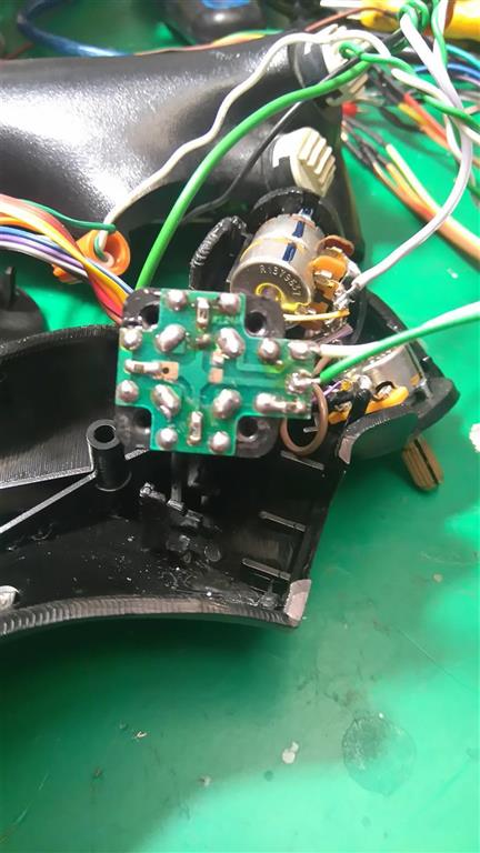
I am using an extra FLCS 4 Way HAT in place of the Eraser Head on the TQS it just fits in the Hole where the Square Eraser Box was. I know from Sokol1's info, it is 4 separate switches really, wired the same as your 4 way Square Hat Switch above, assuming the Black is the Common/GND.
You are right it is taking longer to get the other stuff done than the main wiring so far but I have now moved the X-figher's Handle Button Rings to the Base and also moved the Download Button from the FLCS Base to the X-Fighter Base with an added LED to indicate on/off ...not sure why TM never did it? now I know how easy it was to do. Cutting the new 12mm x19mm hole for it in the Base was pretty easy, I drilled each corner with a small bit and then just "joined the Dots" with a Hobby/Exacto/Olfa Type Knife , the Plastic (ABS?) is softer than I thought , seems softer than the TQS plastic actually.
As you can see in the Pic above I use a Proline White Paint Marker I got at an Automotive/Welding Supply House (Welders use them) to label and mark orientation of the Black Plastic Parts so I can reassemble easily.
wow you have the digital chips of Bob Church! Never was able to get some here in Germany those days, also none of the Thrustmasters I bought over Ebay had some in.
As far as I know, if you use the digital chips, you don't use the PS/2 plug anymore, cause all is programmed via the Gameport, is this right? That's why I never have tried to get the digital chips for my project, cause it isn't possible to get the digital gameport running since win xp.
For my MFD's I have another real antic gear. Mine are the old Quickshot Masterpilots I also had lying around for years, I modified a bit. The Thrustmaster ones are much better, cause they have 20 buttons around the "MFD". Mine have 24 buttons (6 in every row) which is incompatible with most aircraft. That's why my display is not exact in the center. I use one button in every row for other functions and I will leave them black, while the 20 which controls the MFD get white.
Hey, if you are able to fly CAP2, please make a quick report about the feeling of the flight model. I'm also much interested in flying it, but I'm far away of my first flight. Have bought it two months ago in early access state on steam, but on my laptop there is no chance to get it running.
P.S: For what do you need the "Download-Button" on your FLCS? It's connected to the Arduino board now, or am I wrong? The grips PCB is only the shift register board, you could use with an Arduino and a matching software, too. I don't think you need the "Download-Button" at all. Maybe I'm wrong, but it doesn't make sense to me. Or is there a way to download a joystick programming software to the Leonardo board itself (without running the software under windows in the background)? I only have Mega's here, which have to run a software (eg. Mobiflight) in the background. You also have to flash them with the right firmware before you could use them with Mobiflight, but only for one time.
Yes Sorry Viper, I did not make it clear I just moved it to use as a conventional button for something. and since it is an on/off toggle button I added the LED so I would know if I left it ON.
Yes with Bob's Chips you didnt need the Keyboard cable at all but until last week I never cut it off I just curled it up and ziptied it in front, in case I ever needed it for the USB Mod.... that would be a nope
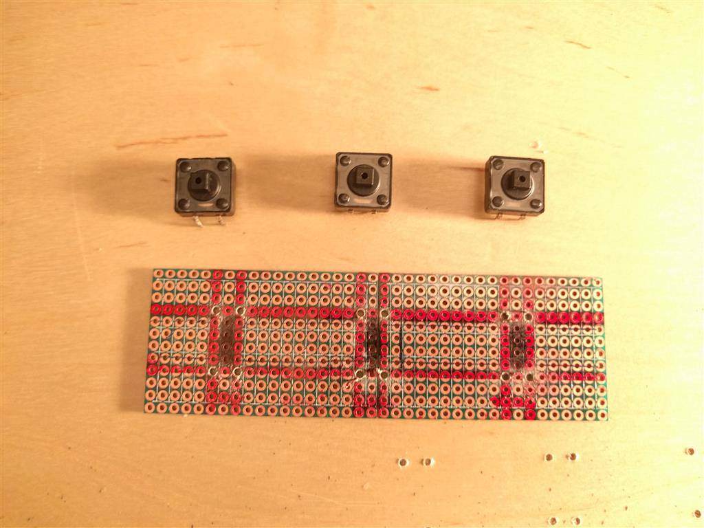
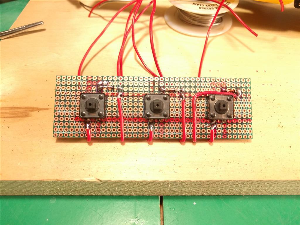
I got around to making the 3 Button PCB for the old X-Fighter Handle buttons last night,basically just a 1x3 button matrix so I could practice how they are done,I used Diodes just to be sure, but it really didn't need to be a matrix AFAIK though.
Now I just need to figure out how to mount it , so the Board it held 3/16" off the Base under the push buttons. I may just mount it on Standoffs,like a Motherboard and just drill a couple more holes in the PCB (Protoboard)and Drill through the Top for the bolts.
They are rather large Tac switches but since they never got much use previously I thought it worthwhile re-using them, since they were rated for joystick use originally , unlike these 10 switches for 10cent ones I see in every Arduino Kit.
Been busy this week so not much progress on the Build/Conversion but Solder Monkey has been kind enough to give me a list of the Buttons,Encoders,Knobs,ProMicros etc He likes to use in his Builds/Conversion .... Much appreciated S.M.
Blue Headers are Clickable links.......... or were when this Post was made in 2017
Oh - and after some playing, don't use rectifier diodes on encoders. Use the 1n148 type. The rectifiers sometimes cancel out the signals in their activation period. 1n148s have a 6 nanosecond period - so you don't loose the pulse.
I use cheap microUSB phone cables 1m or 3 feet from bargaincableusa on ebay for all my mods to splice into the pro micro.
For my gear and the stuff for my friend with the flcs/tqs conversion. I still need to spec out some 3d printed mounts and figure out how to emplace them. His idea of using the wipers from the old pots is great, but it leaves you mounting questions on things like the f-22 pro. Easily solved. Thinking I'm going to end up drilling through the metal mounting flange, tapping it and mounting the board to the flange using the included standoffs. If MegaMozg keeps going the way he has been, we'll probably see tle5014 support or something as the 10/11 series boards die out. If the AliExpress boards stay in production, no reason for him to recreate the wheel for magres axis sensors.
For Base Weights - steel, lead, tungsten in that order. Pennies are zinc - pretty light because of the density. For steel pieces, used weights from "play it again sports" and similar used sporting gear places are great. If you cut the ends off, you have a relatively easy to fit cylinder that fits in the edges of a base. For lead, offer to sweep the floors at a tire center for a few days, provided you keep the lead. Casting lead can be done with a blowtorch or large propane burner. Tungsten, I like the tungsten BB shot from online hunting supply but it's really expensive. I usually use steel and lead. Tungsten is dangerous, more so than lead. Don't try to mill it yourself or use power tools on it.
Had some time on the Weekend , so I now have a functioning FLCS in MMJoy2 , I still need to pack all the Wires and the Leonardo into the Base but everything is working as it should , though one old X-Fighter Pot is spiky so I'll change it for a FLCS one from it's old Base.
Also the Trigger is seen as one button at both 1st stage (guns) and 2nd stage (missle) , not sure if it is my MMJoy2 setup or the wiring at this point though. (Pics below)
Modding the FLCS grip and X-Fighter Gimbal was not to differcult as the screw holes are located in the same positions , I just filed ever so slightly the top of the screw posts to allow the stick to pull fully closed as the X-Fighter Gimbal Shaft has a triangular piece on it which is a bit thicker than the FLCS mount. The Gimbal shaft was also shorten slightly to miss the FLCS Pinky Button , and in the FLCS handle itself I had to carefully file a square slot for the X-Fighter shaft to lock into that the FLCS doesn't have. (see pics below)
***Note the plastics in both Handles are fairly Soft, so a simple metal file and small hacksaw was all it took to get the two peices to mate nicely.
The FLCS Trigger .... it appears I modded or fixed it in the past? , there are several bits of what appears to be part of a plastic container inserted ( margarine anyone ? ) not the original parts...not sure what was there originally though, so pls post a pic or two if you have them of the FLCS Trigger. I'm not not sure if that is why I am seeing the trigger as button 15 in MMJoy2 at both stages or not as yet....
I have started on the TQS too, still need to add the 1N4148 Diodes to each wire in the Handle, but I decided to use the Hat Switch from the X-Fighter instead of a FLCS Hat Switch I have, as it is larger and easier to use. It also has a square base so I was able to make it fit into the Old Eraser Nub Box Holder within the Handle with only slight modification.
***Note/Forewarning..... the original soldering/wires are pretty fragile in the Handle of the TQS, so it was lucky I had taken lots of pics just after opening it as I have now found 3 wires hanging loose and I didn't know where they went to until looking back at my (enlarged) photos and resoldering them.
However I am not familiar with the way the X-Fighter Hat switch is wired with the Cross and SMD Diodes? resistors? and the Blue Resistor/diode on one of the wires, it only has two wires unlike a FLCS Hat switch (5 wires) so I am hoping MMJoy2 will see it once I figure out how to wire it, but it may need totally rewiring ?.
The X-Figthter use resitors because this HAT is connected in one axis - due gameport limitation. So the axis is divided by resitors in several bands, each one correspond to one direction.
For use in MMjoy2 you dont need this, remove that resistors and use diodes. Probable will be more easy remove this entire PCB.
KBird - I took the liberty of hacking your image up. No... I am not an artist
Removing the PCB is a lot of solder to remove, so I left it in place.
Remove all four of those SMD resistors and the through hole resistor on the other side of the PCB.
Remove the old wires.
Now you've got a nice PCB with four switches in a cross.
Diodes and column wires to the outside contacts of the switches.
Wire all the inner contacts and run a wire from the inner loop back to your board as row. You only need to connect all 4 pads, you don't need the fourth side of the loop.
Thanks for the Information Guys , and I really appreciate the "Hacked" Image SolderMonkey that makes it so much easier.
Use 1N4148 Diodes I assume ? since this is basically a 1x4 Button matrix correct ? so I set it up the same way as I did the 3 buttons on the FLCS Base.
Now I look more at the Image my understanding of where to put the Diodes seems backwards , I thought the Diodes went on the Row wire with the stripe toward the Controller Board ? ...funnily I'm looking at my schematic for the 3 button Board I made ,I have them on the Columns (but I wrote Row), That Board is working so I guess my understanding of the Wiki Page was wrong.... and I got lucky when I made the 3 Button Board
Not being into electronics the Fritzing images in the Wiki really didn't make much sense to me though....
Diodes block flow in one direction and allow it in the other. The diode doesn't care if its at the switch, the wire or the arduino. What matters is the direction of flow. Slide the diode across the switch in your mind. You have 1 row loop and four switches with individual wires. The diodes and their directional control have to fit in somewhere, so they get moved to the other side of the switches to the col wires.
Actually that's what I thought ie one direction of flow but when i did a test with a tac switch it worked in MMjoy even with the diode reversed so that just confused me more , so I was actually just online looking at button Matrix webpages to try and understand it a bit better, and if I have it right the Diode should be on the Column wire with the Diode Stripe (black) pointing back up wire to Switch, this page helped me being a non-electronics type...
I realise now the X-Fighter Hat switch is actually 4 tac switches inside a box with a t-shaped "stick" to actuate them , which was leading to more confusion till I open it and realised what your wiring scheme was doing...
between the triggers second stage micro switch and the trigger itself, there is a piece of very stiff foam material. Don't know how it is spelled in english! It's something between rubber and a foam material.
Place it, where your plastic pieces are.
The functions is, that if you press the trigger, the spring presses the first stage and while you press further against this spring, you reach the second stage with the foam material, which activates the trigger stage two.
Have done a lot of working on my pit the last weeks. Finished the overhead, the yoke and the four lever throttle. Now I'm at the F/A-18 throttle which is nearly finished too. Have also integrated all panels in the pit. Next stations are the F-14 throttle, the F-14, F/A-18, AV-8B, AH-1F and AH-1Z grips. If this is done I have to wait for better weather, to sand and paint all the parts.
We never had so much snow the last years and never for such a long period of time. Hope this will finish soon .
between the triggers second stage micro switch and the trigger itself, there is a piece of very stiff foam material. Don't know how it is spelled in english! It's something between rubber and a foam material.
Place it, where your plastic pieces are.
The functions is, that if you press the trigger, the spring presses the first stage and while you press further against this spring, you reach the second stage with the foam material, which activates the trigger stage two.
The "foam" piece was missing or worn out so I replaced it as you see above with some some plastic pieces and both stages are now working but I cannot program the second stage it seems in MMjoy to act as two buttons pressed together, I posted on the MMjoy thread too for advice , so I am still hopeful.
I think you have to seperate the two buttons using diodes, so that the circuit is independent, cause you press two buttons together if you use this originally two stage trigger. If the first button is pressed, the second will be ignored as long as the first still remains pressed.
Simply test it if they work without the mechanic and each one seperate. If so, you could use diodes. With diodes it must run, cause this is the same problem, you have if you use toggle switches. Leo Bodnar has a shematic of a matrix on his web page. But I have seen that you already used diodes in your project, just use them for the trigger too.


![[Linked Image]](http://SimHQ.com/forum/files/usergals/2017/01/full-40431-131181-flcs_hat_switch.jpg)
![[Linked Image]](http://SimHQ.com/forum/files/usergals/2017/01/full-40431-131182-xf_base_btns__1.jpg)
![[Linked Image]](http://SimHQ.com/forum/files/usergals/2017/01/full-40431-131183-xf_base_btns__2.jpg)
![[Linked Image]](http://SimHQ.com/forum/files/usergals/2017/01/full-40431-131184-xf_base_2.jpg)
![[Linked Image]](http://SimHQ.com/forum/files/usergals/2017/01/full-40431-131185-xf_base_4.jpg)