One more technical post, while I still have time.
Last bit of this puzzle is electronics upgrade for my pedals. I decided to publish controller details here to promote excellent service of our ukrainian producer becouse of his excellent product and service.
If you have your DIY projects, specialy if you want to use sensors instead of pots I highly recomend.
His contact : gvl224@ukr.net
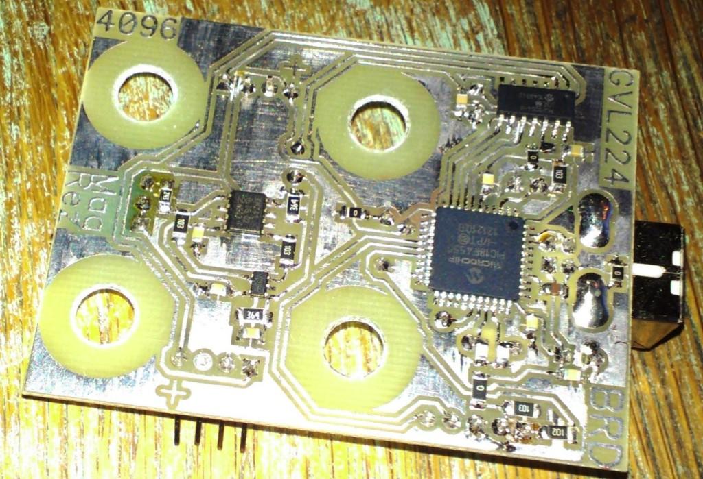
BRD electronics that was used in prototype :

MFG electronics, I just recived pictures, and currently waiting for those to arrive by post :-)
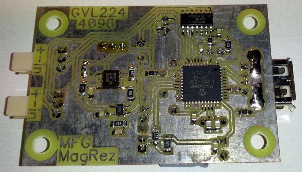

In general, both electronics feature the same hardware and firmware specifications. There is KMZ41 magnetoresistor on board for rudder axis, separate 12bit ADC for a clean signal, autocalibration jumper, trimmer pot for adjusting magnetoresistor axis middle voltage, and 2x axis for brakes.
So what did we modify for my pedals :
1. Screw holes - stronger holdown of controller becouse on old one USB plug was far away from screws.
2. USB plug from Usb B ( printer) to usb A - lower profile...use of USb extension cables
3. everything on controller made to "low profile"
4. Brakes axis position
5. Brake axis connector
6. Firmware - windows read 4096 positions, old one read 65 000 positions and I wanted to present a true positions
7. Dimensional change
8. Windows Name change, now it is "MFG Simundza - rudder"
So why these mods :
Low profile was necessary to integrate sensor in a proper distance from magnet. This gives me more resolution than prototype board.
I put brakes axis on the back becouse cables go out there now. I also wanted easy brakes cable exchange or unplug in the future...no need to disassemble complete pedals to unplug cable. For this reason there is a different connector, more common in sensors and end user cannot plug it wrong way...This is all made to be future proof...maybe you will need to replace worn out cables in 7-10 years, or some servicing need in the future...who know...this makes it easier.
For a firmware I think it is better to see true raw values than full windows resolution..becouse it's real values, and also becouse smaller numbers make it easier to adjust brakes deadzone which is necessary becouse of the way my mechanical buletproof sensor reading design works. Shortly...every time you adjust pedal angle you need to readjust brakes calibration - becouse sensor didn't move...only pedals did.
USB A was choosen becouse of low profile and easy to find spare cable if you somehow destroy original. Proto board used USB B printer connector...and spare cable for that one usualy have ferrite shield - becouse it's made for printer. It's not good for game controller purpose.


