|
#4314587 - 11/23/16 03:59 PM
 Re: Open Hardware Joystick
[Re: S_Bartfast]
Re: Open Hardware Joystick
[Re: S_Bartfast]
|
Joined: Nov 2016
Posts: 26
S_Bartfast

Junior Member
|
Junior Member
Joined: Nov 2016
Posts: 26
South Australia
|
Okay, so I have a first sketch of a design for this stic. This is what I have at the moment: ![[Linked Image]](https://dl.dropbox.com/s/g8lt5yqwcay7trf/Centre.jpg) There are 3 components coloured dark, medium and light grey which are connected with 6x10x3mm bearings. The dark grey piece can pitch forward 10 degrees and pull back 25 degrees inside the medium grey piece, and pivots 50mm below the roll axis: ![[Linked Image]](https://dl.dropbox.com/s/c6qn7iz9aybhjlq/Dive.jpg) ![[Linked Image]](https://dl.dropbox.com/s/8vta7cvkzez8c5r/PullUp.jpg) The medium grey piece has 17 degrees roll available inside the light grey piece: ![[Linked Image]](https://dl.dropbox.com/s/5lg4l6nezda3af8/Roll.jpg) And this is how the stick looks in the top-left corner: ![[Linked Image]](https://dl.dropbox.com/s/1rhg2y1zkd86zc4/Spin.jpg) I'm not too sure of how the centreing mechanism's going to work just yet but as a first pitch I've just got three pegs and springs are to be stretched between these pegs: ![[Linked Image]](https://dl.dropbox.com/s/td1dvyskj2vnckf/Spring-neutral.jpg) I don't know how well this is going to work as it is just a first draft but you know, it's something to build on: ![[Linked Image]](https://dl.dropbox.com/s/gtq5b44k909fv5o/Spring-forward.jpg) ![[Linked Image]](https://dl.dropbox.com/s/5p6emdq4zhrh4ma/Spring-back.jpg)
Last edited by S_Bartfast; 03/28/17 08:05 AM.
|
|
|
#4314789 - 11/24/16 05:34 AM
Re: Open Hardware Joystick
[Re: LocNar]
|
Joined: Nov 2016
Posts: 26
S_Bartfast
Junior Member
|
Junior Member
Joined: Nov 2016
Posts: 26
South Australia
|
Looks good, though that sharp corner (Shempp Hirth?) is aimed straight at your balls :o Hehe, I thought about that too, and momentarily thought how it could be potentially disastrous in a crash - then realised it's just a simulator  This curve isn't actually based on anything it was just a means to draw the grip back 5" (125mm), though I did partially get inspiration from the grip in the heli-chair. The idea though is to have the pole removable so that one can easily exchange it if so desired: ![[Linked Image]](https://dl.dropbox.com/s/jrvnozexexmtlg6/Sticky-800.jpg) If you use this type of spring centering you will need very hefty springs which will take much more space than you have allotted for them, and req much more robust pins to support them.
Design-wise, you want the angle the springs form relative to the direction they are pulling to be much shallower than that. There is an exponential decrease in efficiency (spring applying force the direction you want) as you diverge from pulling perfectly in-line (180deg), and at the angles you have you are well up that curve already. I agree, the centering mechanism is very poor. I did have the springs more opposed to each other at first but was then concerned that when one spring was extended their wasn't actually enough room for the other spring to compress so rearranged them to how they are now but I agree, it's a pretty poor implementation. I've been trying to think of a neater/better way of working these springs and will probably opt for a CAM design (as all the serious projects seem to do) but at the moment I'm just having a little trouble visualising how exactly it works. I figured I'd just start off with slapping springs directly to the pins and figure out how to attach CAMs in due course  By the way, are their any joysticks that have mechanical trims built into them? I figured the trim in a real aircraft would actually adjust the neutral/resting location of the stick (as in cause the stick to come to rest somewhere not necessarily in the center of its travel). I take it the digital trims we use in our flight sims just adjust what input the neutral location of the joystick represents without actually physically changing the location of where the stick comes to rest. Is that correct? Are there any joysticks that do change the resting location? I figure it could be done by placing those CAM/Spring pins on a plate that the operator can rotate with either a wheel or a lever of sorts: ![[Linked Image]](https://dl.dropbox.com/s/1pc448hswoeqdfv/Trim-800.jpg) Possibly fly-by-wire aircraft actually do use digital trims that do not affect the stick location and for those it would be fine to simply use the trim in the simulator but for a real glider I'm pretty sure the rest location of the stick would have to be affected by the trim setting.
Last edited by S_Bartfast; 03/28/17 08:06 AM.
|
|
#4314793 - 11/24/16 06:17 AM
 Re: Open Hardware Joystick
[Re: S_Bartfast]
Re: Open Hardware Joystick
[Re: S_Bartfast]
|
Joined: Nov 2016
Posts: 26
S_Bartfast
Junior Member
|
Junior Member
Joined: Nov 2016
Posts: 26
South Australia
|
By the way, are their any joysticks that have mechanical trims built into them? I figured the trim in a real aircraft would actually adjust the neutral/resting location of the stick (as in cause the stick to come to rest somewhere not necessarily in the center of its travel). I take it the digital trims we use in our flight sims just adjust what input the neutral location of the joystick represents without actually physically changing the location of where the stick comes to rest. Is that correct? Are there any joysticks that do change the resting location? I figure it could be done by placing those CAM/Spring pins on a plate that the operator can rotate with either a wheel or a lever of sorts: https://dl.dropboxusercontent.com/u/84843025/Image%20Cache/Cockpits/50mm-offset/Trim-800.jpgAfter re-reading LocNar's first post I see he was discussing something simular to this but using a "torsion spring" rather than a modifying the balance points of CAMs. Do you have any more details LocNar? Your approach sounds relatively straightforward. Here's what LocNar said again to save hunting back: I also have a design for a static centering gimbals, that copies the trim mechanism from my SZD-59, which uses a long torsion spring acting on the stick in pitch, which you can adjust by setting it in one of several notches fore/aft along a plate adjacent to the stick, though it kind of digs into your thighs the trimmable speed range with it is from stall to a speed higher than I'm comfortable letting the plane fly itself at.
|
|
|
#4314843 - 11/24/16 12:13 PM
Re: Open Hardware Joystick
[Re: S_Bartfast]
|
Joined: Nov 2001
Posts: 3,955
Sokol1
Senior Member
|
Senior Member
Joined: Nov 2001
Posts: 3,955
Internet
|
By the way, are their any joysticks that have mechanical trims built into them? I figured the trim in a real aircraft would actually adjust the neutral/resting location of the stick (as in cause the stick to come to rest somewhere not necessarily in the center of its travel). I take it the digital trims we use in our flight sims just adjust what input the neutral location of the joystick represents without actually physically changing the location of where the stick comes to rest. Is that correct? Are there any joysticks that do change the resting location? I figure it could be done by placing those CAM/Spring pins on a plate that the operator can rotate with either a wheel or a lever of sorts: https://dl.dropboxusercontent.com/u/84843025/Image%20Cache/Cockpits/50mm-offset/Trim-800.jpg CH joystick gimbal has mechanical trims in similar way to your drawing, although they are just a DOS era legacy, when they are need for calibration process, since CH are all "vintage" (design, electronics..) from 1990's, are more cheap continues produce the trim that change the molds for remove. You find CH soft "guru" Bob Church post (there on in CH Hangar, don't remember) recommend don't use that trims in USB sticks, seems because are liming the axis resolution in one side of the gimbal. Since you have R/C background, CH gimbal use the same mechanics of old Futabas gimbals, before the "digital" trim. Too bad that Sukhoi forum are now dead, or you will see that all this center mechanism, spring positions that you are "studying" there are done in that forum at ~10 years ago and the conclusion: CAM Gimbal.  BTW - Talking in CH gimbal, this "thing" rusting there is a "scaled up" CH gimbal done at 10 or more years ago by a colleague and a mechanic machinist used to build experimental aircraft.  Was done for dogfights in IL-2 Sturmovik, and for me result horrible for this purpose, very "cluck" and the big leverage amplifies gimbal play. I think with some tuning are suitable maybe for FSX "flights". In a way I've inherited it - the guy leave there for install new USB circuit (at time use gameport) but meanwhile lost interest in "computer flights"... By myself it goes to the trash, but the garbage truck does not carry it. I just remove their Thrustmaster FCS B-8 like grip. "Rust in pieces". Curiosity: Industrial joystick gimbal inside view, with "piston" spring system Saitek like and big... pot'. https://www.youtube.com/watch?v=MCDsge-3z0U
|
|
|
#4315595 - 11/27/16 01:43 PM
Re: Open Hardware Joystick
[Re: Sokol1]
|
Joined: Nov 2016
Posts: 26
S_Bartfast
Junior Member
|
Junior Member
Joined: Nov 2016
Posts: 26
South Australia
|
Wow, that is some serious joystick porn!
Last edited by S_Bartfast; 11/27/16 10:10 PM.
|
|
|
#4315771 - 11/28/16 09:09 AM
Re: Open Hardware Joystick
[Re: S_Bartfast]
|
Joined: Nov 2016
Posts: 26
S_Bartfast
Junior Member
|
Junior Member
Joined: Nov 2016
Posts: 26
South Australia
|
After making this prototype I began to get concerned that 10� forward pitch might not be enough. 10� really is a small deflection and it feel strange to think that is all that's available. It's no doubt correct for a glider but it would seem hard to fly other types of aircraft with such limited forward movement, so I decided to do a bit of a re-design. I ended up deciding to make the joystick capable of providing symmetrical deflection but implementing bolts that can be adjusted to limit the range. The idea is that the more you screw the bolts in the more the joystick's movement is restricted in that given direction: ![[Linked Image]](https://dl.dropbox.com/s/qhjqvd6fk20546f/BoltLimit-800.jpg) This shows the setup for a limit of 10� forward: ![[Linked Image]](https://dl.dropbox.com/s/1qm1zk093t8lekw/BoltLimit-dive-800.jpg) 25� backward: ![[Linked Image]](https://dl.dropbox.com/s/ie4y9956vdba8fk/BoltLimit-climb-800.jpg) And a left/right deflection limit of 17�: ![[Linked Image]](https://dl.dropbox.com/s/qeywuc2zmk5672q/BoltLimit-roll-800.jpg)
Last edited by S_Bartfast; 03/28/17 08:12 AM.
|
|
|
#4316046 - 11/29/16 03:14 AM
Re: Open Hardware Joystick
[Re: Falstar]
|
Joined: Nov 2016
Posts: 26
S_Bartfast
Junior Member
|
Junior Member
Joined: Nov 2016
Posts: 26
South Australia
|
Thanks Rob  Is there a reason that 3 of the bolts have the jam nut on the outside, but 1 on the inside. Is it to provide a longer stop at the top? In short, yes. The idea is that the holes for the bolts through the 3mm plate will in fact be threaded (such that the bolts will actually 'screw through' the plate) and the additional nut on the outside is, as Falstar correctly surmises, a 'jam-nut'. Once the bolt has been threaded through enough to limit the joysticks throw to the correct amount the jam-nut is synched up to the plate to provide tension and prevent the bolt from winding in or out unintentionally. The two lower bolts have the jam-nuts on the outside because there simply isn't space to have them on the inside. The two upper nuts were originally on the inside (as their wasn't enough space on the outside) but when I came to wind that rear bolt out to allow the 25� deflection I found the stick was hitting the nut rather than traveling the full range that was intended. The simple solution to this was to place the nut on the other side of the plate however this necessitated cutting away some of the lighter-grey piece to provide clearance for the nut, which is why the upper bearings are now in the centre of those semi-circular 'ears'. After I made the modification I then found when I wound the front bolt all the way in to restrict the forward travel to 10� their wasn't enough space between the head of the bolt and the plate it was screwing into for the nut, so this nut was relocated back to the inside again where there was plenty of space. As these nuts are 'free-spinning' nuts (in that they aren't actually attached to the main work piece) and don't carry any significant load they can be easily swapped around or replaced with thinner low-profile nuts which is common for jam-nuts, or even left off entirely�it really doesn't matter. By the way, these bolts are actually M5 bolts and the ones depicted are 30mm long. These bolts are surprisingly tiny when you come to hold them in your hands. Infact many of the components were smaller than I was expecting when I came to make them. I know what the dimensions were when I was designing it and I've thought about them a fair amount but you get so use to looking at zoomed in images on a large monitor that you tend to forget how small 3mm actually is The good news though was that although components were at times surprisingly small it all seemed to function as I'd expected
Last edited by S_Bartfast; 11/29/16 03:25 AM.
|
|
|
#4326650 - 01/07/17 04:41 PM
Re: Open Hardware Joystick
[Re: S_Bartfast]
|
Joined: Nov 2016
Posts: 26
S_Bartfast
Junior Member
|
Junior Member
Joined: Nov 2016
Posts: 26
South Australia
|
Well, I started a new job recently which is great because not only will I be able to feed myself again but should be able to afford to buy joystick stuffs. However, this has unfortunately also meant I havn't been able to devote as much time to this project as I would like, but I have been thinking things over when I can. The next thing to work out has been a proper way of implementing the centering springs. I have actually spent a lot of time pondering this and while I very much like the look of the "Zagruzathelli/lya" system I'm not so sure I'll be able to make it work myself, so have been considering a 'Scissor' design as used in RC transmitters: ![[Linked Image]](https://static.rcgroups.net/forums/attachments/3/5/3/3/0/a9557344-35-FRAMEASSEM.jpg) A user called 'ZAGNUT' on the 'RCGroups' forum kindly uploaded some detailed designs of a gimbal mechanism as used in RC transmitters. While it has taken a lot if thinking to get my head around (and I'm still not convinced that I understand how it works fully) it has nevertheless given me inspiration to design my own system: ![[Linked Image]](https://dl.dropbox.com/s/1c6c0bmlmy01ynm/Scissors%20-%20high.jpg) ![[Linked Image]](https://dl.dropbox.com/s/v3oy1uzy0d088k6/Scissors%20-%20low.jpg) The idea is that the two sides of the movement are meant to be able to swing independently but there is a spring across the top pulling the halves closed. There are then going to be pins on the stick which will pry the mechanism open as the stick is deflected away from the centre: ![[Linked Image]](https://dl.dropbox.com/s/sl333x4nlqvtzlx/ScissorsPins.jpg) Here is an image of the mechanism mounted on the stick in the upright position: ![[Linked Image]](https://dl.dropbox.com/s/hy1s3sxb21x47yk/scissors-upright_800.png) Full forwards: ![[Linked Image]](https://dl.dropbox.com/s/vfil1fycad445gz/scissors%2B10_800.png) And full back: ![[Linked Image]](https://dl.dropbox.com/s/6i0h6r6dy34kvzc/scissors-25_800.png) And finally here is an animated GIF of the stick being thrown from full back to full forward: ![[Linked Image]](https://dl.dropbox.com/s/hjrupg9juf55vof/scissors.gif) I have no idea if this will work properly on a full sized joystick but it seems to work well enough in RC transmitters. Another fortunate attribute of this design is that both the fore and aft movement is resisted by the same spring so there wouldn't be any asymmetry concerns as mentioned by Sokol1. We'll just have to try it and see if it works
Last edited by S_Bartfast; 03/28/17 08:19 AM.
|
|
|
#4326696 - 01/07/17 06:58 PM
Re: Open Hardware Joystick
[Re: S_Bartfast]
|
Joined: Nov 2012
Posts: 161
LocNar
Member
|
Member
Joined: Nov 2012
Posts: 161
|
Classic 'pincher', 'tweezer', 'opposing rocker arm' design, found in many devices, mostly because it's easy to manufacture however this type of centering will be very un-glider feeling, at least in roll where you cross the center frequently. This method creates a pronounced/sharp 'clack' as you cross the center as the load transfers from one lever to the other. Softer materials can make it less pronounced but it will never go away. Net result: it would drive me -crazy- trying to center a thermal, feeling and hearing tack tack tack tack tack tack tack... Honestly the plain old simple opposing spring idea you were going with a while back was a better design for what you are trying to accomplish, especially if you also incorporate damping with it as well. Ether hydraulic (motorcycle steering dampers are popular but bulky, rotary ones like on VO101MMaister's cost a fortune) or simple mechanism of sliding parts under pressure using damping grease ('thick' does not = damping) like Nyogel 767a, like VKB has adopted on their mechanisms. Almost as important for realistic feel. Unless I'm mis-remembering what why it was brought up, asymmetry concerns relate to cam centering, specifically designs like VKB where the bearing drives the cam and the cam pivots from one side. Those can not use a simple symmetrical profile because of the changing leverage depending on if the drive bearing is moving towards or away from the pivot (lever getting bigger vs lever getting smaller), so the profile is modified to offset the variable leverage.   However, if the cam drives the bearing like VO10Maister (and later Monoblok/VPC), the cam is then symmetrical because there is no changing lever length in the tensioning mechanism regardless which way it swings. 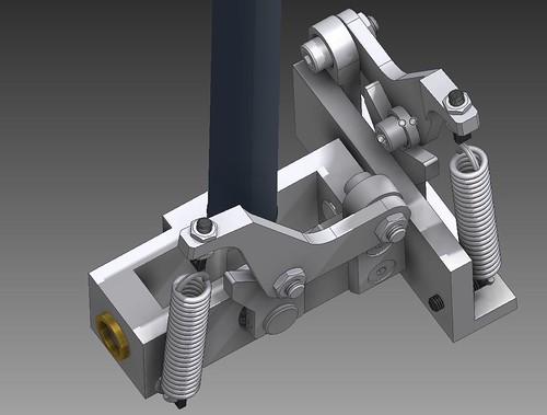  There is also Baur's mechanisms, which originally used 2 simple opposing cams originally to keep loads symmetrical (though his later cams were given offsets to be actually symmetrical),  and another version that I've only seen a few examples of, is Romer's design here: https://youtu.be/JtroF-BjAc8
|
|
|
#4328480 - 01/14/17 02:38 PM
Re: Open Hardware Joystick
[Re: S_Bartfast]
|
Joined: Nov 2016
Posts: 26
S_Bartfast
Junior Member
|
Junior Member
Joined: Nov 2016
Posts: 26
South Australia
|
Hmm, I see what you are saying. With this design there definitely is contact and separation of components as one crosses the centre. While I would think that if you were to get the tolerances just right there should be a constant tension across the center there would however undoubtedly be a 'tack' sound and quite possibly a small tactile 'knock' as the components come into contact with each other. How irritating! I would think that it should be possible to eliminate the slop in the center with very precise engineering/tolerances but there is no way of avoiding the fact that components are coming into and leaving contact with each other across that center. How disappointing  . So I've been scratching my head about things again and have spent the last week or so pondering exactly what the curve of that CAM lever (or whatever) should be, and I'm pretty sure that even in VO10Maister's design the CAMs should be at least partially asymmetrical. This is because as the bearing is pushed up it will also be swung away from the centre line, precisely because the lever arm stays the same length. As in, as the stick is pulled forward (or pushed backward) and the CAM on the stick pushes that bearing up, the bearing will not only rise due to being pushed up by the CAM but it will also be swung away from the centre line by the lever arm and will therefor no longer be directly above the pivot point of the joystick. This means the curve of the CAM will likewise need to be 'shifted' to the side by the same amount in order to cause the same deflection of the lever arm. If the bearing were simply pushed up and always remained on the centre line the CAM profile would indeed be symmetrical however as it is both CAMs profiles will need to be 'bent' in the same direction. The degree of asymmetry may well be less than that required by the 'CAM lever' design but the curves on the CAMs will indeed need to be 'bent' towards the 'hinge' of the lever arm at least a little as the CAM profile gets 'higher' in order to maintain similar spring tension. This will have the effect of flattening out one side and raising the apparent steepness of the other, thus making the CAM profile asymmetrical :s I implemented the mechanism on my joystick but have it inverted such that the CAM is on the end of the stick pointing down rather than on the side of the stick pointing up. This is what it looks like at 10� forward with the CAM leaver up against the bottom of the stick: ![[Linked Image]](https://dl.dropbox.com/s/neyab4o9vq2c11e/Spring%2B10.png) And this is what is looks like with the stick 10� back with the CAM leaver in exactly the same position: ![[Linked Image]](https://dl.dropbox.com/s/c9jdg21j2cvc2yk/Spring-10.png) As can be seen the bearing is clearly separated from the CAM in the second image meaning if the CAM were to be swung up such that the bearing were to make contact with the CAM there would be significantly less spring tension acting on the lever. Does anyone know a good way to calculate exactly what the profile of that CAM curve should be? I've been trying to work it out in my head but I'm afraid my talent for calculating such equations is not as strong as it otherwise could be. Ideally I would like a curve that for every degree of deflection of the stick will result in exactly 1mm of spring tension. Hopefully if I can get an equation for the curve I'll be able to print it out on a printer then glue it to a piece of steel then ever so carefully carve it out with an angle grinder .
Last edited by S_Bartfast; 03/28/17 08:21 AM.
|
|
|
#4328485 - 01/14/17 02:54 PM
Re: Open Hardware Joystick
[Re: LocNar]
|
Joined: Nov 2001
Posts: 3,955
Sokol1
Senior Member
|
Senior Member
Joined: Nov 2001
Posts: 3,955
Internet
|
However, if the cam drives the bearing like VO10Maister (and later Monoblok/VPC), the cam is then symmetrical because there is no changing lever length in the tensioning mechanism regardless which way it swings.
I believe that V0O101Maister and Monoblock profile is not symmetrical, maybe not too noticeable due their straight profile. VKB use progressive profile - by user request - to create "feel" of weight across the movement. Soon will offer more "linear" profiles as option. In Baur double CAM only the side in extremity force against the spring, the other side became just a stop, so you have the same profile in each side.
Last edited by Sokol1; 01/14/17 02:56 PM.
|
|
|
|
|
|
|
|
|
|
|
|
|
|
|
|
|
|
|
|
|
Exodus
by RedOneAlpha. 04/18/24 05:46 PM
|
|

![[Linked Image]](https://dl.dropbox.com/s/uqvqjvvfj9v5hbi/InThePaw-800.jpg)
![[Linked Image]](https://dl.dropbox.com/s/bnxmy8l5t69b6kb/Ring-dimen-800.jpg)
![[Linked Image]](https://dl.dropbox.com/s/i3i8v5dee2gon9j/Bucket-dimen-800.jpg)
![[Linked Image]](https://dl.dropbox.com/s/7vs9506elw0aiy3/Sticky-dimen-800.jpg)
![[Linked Image]](https://dl.dropbox.com/s/onl5z7q0xwwh227/Pieces-800.jpg)

