|
#4335561 - 02/08/17 06:23 PM
 Re: MMJoy/MMjoy2 - Build your own USB controller
[Re: SolderMonkey]
Re: MMJoy/MMjoy2 - Build your own USB controller
[Re: SolderMonkey]
|
Joined: Dec 2016
Posts: 454
Kb1rd1

Member
|
Member
Joined: Dec 2016
Posts: 454
|
erichos - stick build looks fantastic! The TLE5010 sensors from AliExpress arrived for me last night. Turnaround time on the order was only 15 days. What arrived is a little different from the images that Sokol put up. Most interesting, the magnets are disks with proper poles 4mm in diameter. The boards are hand soldered and have fibers on them from flux cleanup.  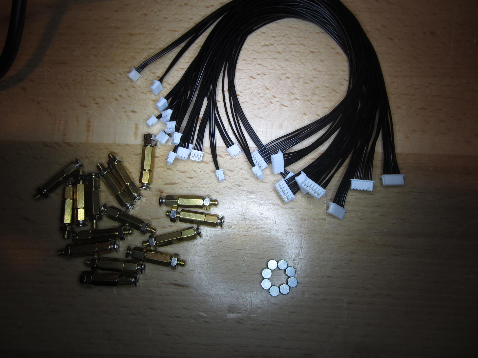 I would urge you to inspect your boards prior to firing them up. As I was looking at each one... found this lovely bridge. Easy fix, but don't know what it would do with 'lectricity on it.  All in all, I'm satisfied with the boards. They're populated and assembled for less than I can source boards and parts myself. My TLE5010's have finally gotten through Customs and are the same as SolderMonkey's with the slotted PCB and a small magnet included. On 1st inspection I do not see any bad soldering as some others mentioned either. Is there a guide somewhere on how to install in thees in a Joystick and then set these up in MMJoy2 somewhere? I do see on Mega-Mozg Pinout pic that Pin 10 [B6] should be used and I see SCK,MOSI etc on the TLE5010 PCB but I am not sure how the (2) J3 connectors ( I think they are called J3's) are used or perhaps they are just cut off and dupont pins or sockets added ? Or is there another PCB/Breakout Board I was supposed to Order too? Thanks again Guys... KB. Edit : I found a little info starting on page 29 of the Thread , and a little more on pg30 and pg31 too like this from Mega-Mozg.... "B6" for TLE5010-GEN - this pin are shared for all TLE5010/5011 sensors. "B3" for SPI-MISO - this pin are shared for all "SPI" sensors (TLE5010/5011/kma200/mcp3201-3208). "B1" for SPI-SCK - this pin are shared for all "SPI" sensors (TLE5010/5011/kma200/mcp3201-3208). "SPI-CS" - you can connect as you like, and where you connect CS-pin need to setup at configurator. this pin are individual to sensor. (F4 & F5 - just a sample). also additional data line "SPI-MOSI" shared for "SPI" sensors mcp3202-3208. Read more: http://simhq.com/forum/ubbthreads.php/topics/4101926#ixzz4Y7Yf4dVU
Last edited by Kbird; 02/08/17 06:49 PM.
|
|
#4335584 - 02/08/17 08:21 PM
 Re: MMJoy - Build your own USB controller
[Re: mega_mozg_13]
Re: MMJoy - Build your own USB controller
[Re: mega_mozg_13]
|
Joined: Feb 2017
Posts: 2
Alphalori
Junior Member
|
Junior Member
Joined: Feb 2017
Posts: 2
KIEV, Ukraine
|
Ok. I'm not a profi in programming, but tried to find a simpler workaround to use Ledcontrol utility. This is Autohotkey software, that allows to assign scripts on keyboard/mouse/joystick controls and even compile scripts to an *.exe I'll just leave here a piece of script which switches 2 LEDs via buttons-press. Maybe somebody will need it. DEVID=8888
PID=8888
vPATH=c:\mmjoy2
1Joy17::;button 17 of Joystick #1 pressed (assigned to Landing gear)
if vGear=0 ;vGear variable to remember the last state on/off of Landing Gear
{
Run %vPATH%\ledcontrol.exe %DEVID% %PID% 003 255 0 0, min
vGear=1
sleep, 500
Process, Close, LEDcontrol.exe
Run %vPATH%\ledcontrol.exe %DEVID% %PID% 001 255 0 0, min
sleep, 500
Process, Close, LEDcontrol.exe
}
else
{
Run %vPATH%\ledcontrol.exe %DEVID% %PID% 003 0 0 0, min
vGear=0
sleep, 500
Process, Close, LEDcontrol.exe
Run %vPATH%\ledcontrol.exe %DEVID% %PID% 001 0 0 0, min
sleep, 500
Process, Close, LEDcontrol.exe
}
Return
1Joy18:: ;button 18 of Joystick #1 pressed (assigned to Cargo scoop)
if vScoop=0 ;vScoop variable to remember the last state on/off of Cargo Scoop
{
Run %vPATH%\ledcontrol.exe %DEVID% %PID% 004 255 255 0, min
vScoop=1
sleep, 500
Process, Close, LEDcontrol.exe
Run %vPATH%\ledcontrol.exe %DEVID% %PID% 001 255 255 0, min
sleep, 500
Process, Close, LEDcontrol.exe
}
else
{
Run %vPATH%\ledcontrol.exe %DEVID% %PID% 004 0 0 0, min
vScoop=0
sleep, 500
Process, Close, LEDcontrol.exe
Run %vPATH%\ledcontrol.exe %DEVID% %PID% 001 0 0 0, min
sleep, 500
Process, Close, LEDcontrol.exe
}
Return
|
|
|
#4335902 - 02/09/17 10:17 PM
Re: MMJoy - Build your own USB controller
[Re: Sokol1]
|
Joined: Jan 2017
Posts: 5
Penzija
Junior Member
|
Junior Member
Joined: Jan 2017
Posts: 5
Bosnia and Herzegovina
|
Sorry for the blurry picture, i had no better camera at that time.
Sadly you're right about the magnets, at least for me, I had to glue them on this way to get the sensor to work.
It could be that they are shipping now other magnets with the new boards but you'll have to get that confirmed by someone else.
Last edited by Penzija; 02/10/17 08:01 PM.
|
|
|
#4335908 - 02/09/17 10:48 PM
Re: MMJoy - Build your own USB controller
[Re: Penzija]
|
Joined: Dec 2016
Posts: 454
Kb1rd1
Member
|
Member
Joined: Dec 2016
Posts: 454
|
Sorry for the blurry picture, i had no better camera at tat time.
Sadly you're right about the magnets, at least for me, I had to glue them on this way to get the sensor to work.
It could be that they are shipping now other magnets with the new boards but you'll have to get that confirmed by someone else. Thanks for replying and confirming the Magnet orientation Penzija , I will just have to hook one up and try things.... I just didn't want to fry anything by accident , I am new to USB Joystick modding and electronics in general so just being careful. KB.
|
|
|
#4336158 - 02/10/17 08:08 PM
Re: MMJoy - Build your own USB controller
[Re: Kb1rd1]
|
Joined: Jan 2017
Posts: 5
Penzija
Junior Member
|
Junior Member
Joined: Jan 2017
Posts: 5
Bosnia and Herzegovina
|
I'm glad if I can help, I had the board multiple times wrongly connected, even had the polarity wrong and it still works so i think theres no need to worry about frying it by a minor accident. Why cant you attach the board like I did? Why not attach it like this?  Hope my drawing skills are not too bad
|
|
|
#4336228 - 02/11/17 01:12 AM
Re: MMJoy - Build your own USB controller
[Re: Penzija]
|
Joined: Dec 2016
Posts: 454
Kb1rd1
Member
|
Member
Joined: Dec 2016
Posts: 454
|
|
|
|
#4337719 - 02/15/17 07:44 PM
Re: MMJoy/MMjoy2 - Build your own USB controller
[Re: Kb1rd1]
|
Joined: Apr 2016
Posts: 63
erichos
Junior Member
|
Junior Member
Joined: Apr 2016
Posts: 63
Slovakia
|
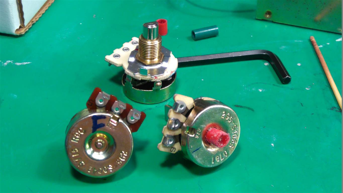
The TLE5010 are wired and working but I still am figuring out how to mount them as I am not 100% happy with the action of the FLCS Pot after I enlarged the hole in the back of it to accept the Pen plastic tube above , the action is not very smooth as it seems the Pot is now riding on the epoxy/new hole edge but I think I can just use the Pot Shaft without the metal housing with some spacer washer instead.
KB
Yes Kbird, I used the pot shaft only without metal housing on my CH Fighterstick where is the same pot like your. And is working OK.
|
|
|
#4338056 - 02/16/17 08:41 PM
Re: MMJoy/MMjoy2 - Build your own USB controller
[Re: erichos]
|
Joined: Dec 2016
Posts: 454
Kb1rd1
Member
|
Member
Joined: Dec 2016
Posts: 454
|
The TLE5010 are wired and working but I still am figuring out how to mount them as I am not 100% happy with the action of the FLCS Pot after I enlarged the hole in the back of it to accept the Pen plastic tube above , the action is not very smooth as it seems the Pot is now riding on the epoxy/new hole edge but I think I can just use the Pot Shaft without the metal housing with some spacer washer instead.
KB
Yes Kbird, I used the pot shaft only without metal housing on my CH Fighterstick where is the same pot like your. And is working OK. Thanks Erichos ,I am trying that now, the TLE5010 are turning out to be more work than I thought to get installed , so it is going slowly . Do you know how to wire a 1P12T Rotary switch for use with MMjoy ? I assume I need diodes (1N4148) can I add one to the common wire or do I need to add 12 , one to each Throw wire? Can the 12 throw wires be connected to make a button matrix ? using only 2 pins on the arduino or do you need to wire each throw seperately ? I may not have enough pins for that but perhaps a 2x6 matrix instead of a 1x12 may work better since I already have 4x4 matrix in the TQS. Thanks again for your help , appreciate it. KB.
|
|
|
#4338368 - 02/17/17 06:27 PM
Re: MMJoy/MMjoy2 - Build your own USB controller
[Re: erichos]
|
Joined: Dec 2016
Posts: 454
Kb1rd1
Member
|
Member
Joined: Dec 2016
Posts: 454
|
Hi Kbird,
rotary switch works as 12 single switches. But witch 1 common contact that you have to use as common ROW (or COLLUMN) and you have to use 1 diode for every switch position = 12 diodes. But MMJoy2 knows only 10x10 matrix button so either you use only 10 position of rotary switch or use board with shift registers to connect this rotary switch and you need no diodes then. It is the best solution. Or this rotary switch you can set for only 10 positions easily, there is a washer with such jut and move this washer to position for 10 and you have 10-pos rotary switch. I had forgotten that MMJoy2 only supports a 10x10 Button Matrix , I actually wanted a 1P10T switch to use in CAP2 for the AV8B Nozzle Angles but could not find one, but I was aware of the Nut to allow a change in a Rotary Switch's Throw Number but I don't see something like that on this switch unfortunately ,it didn't even come with a Panel Retaining Nut for mounting. I guess I could just not wire 2 positions , but I am not sure I have 10 input pins left or can the 10 positions be wired together with 1 common to a sigle pin? ie a 1x10 matrix?   I do have some 74HC165 Shift Registers, so I guess it is time to learn how to mount one on some Proto Board and use them in MMJoy2 or do you need a dedicated PCB to mount them and wire them for MMJoy? Thanks again for you help Erichos , it's been invaluable for me so far in this Mod. KB.
|
|
|
#4338413 - 02/17/17 08:50 PM
Re: MMJoy/MMjoy2 - Build your own USB controller
[Re: Sokol1]
|
Joined: Apr 2016
Posts: 63
erichos
Junior Member
|
Junior Member
Joined: Apr 2016
Posts: 63
Slovakia
|
Kbird, you have type of rotary switch that you can not set, Sokol is right, I thought that you have another one.
So you can use only 10 positions, you can use either 1 ROW and 10 COLs or 1 COL and 10 ROWs, it is up to you. Connect it like 12 switches, it is the same, you need button matrix 1x12 not 2x6 not 4x4... because you have only 1 common pin. If you do not understand it I will post you scheme. Let me know. But in this case the best solution is to use the shift registers because there all switches have only 1 common pin - ground, it is very useful for rotary switch. And you need only 2 arduino I/O pins for connecting all switches (plus VCC, GND and SCK of course), 24 or 64 and so on, max. 96 switches for 1 board with ShRegs. You can mix it, some pins for button matrix and others for ShRegs. PCB is in folder /MMJoy2/PCB/
Bye
|
|
|
#4338455 - 02/17/17 10:49 PM
Re: MMJoy/MMjoy2 - Build your own USB controller
[Re: Sokol1]
|
Joined: Dec 2016
Posts: 454
Kb1rd1
Member
|
Member
Joined: Dec 2016
Posts: 454
|
Ok Thanks Sokol and Erichos , my mistake, they had two types, one was plastic ( like Sokol's pic) so I went with the stronger looking Metal one not knowing the differences,(noobie mistake). I am not sure the plastic one was on-MOM-on-MOM though , do I need that? or can I make current switch work?. I had not thought about it being always on in the game...not good... It was not to expensive so I can pick up another one, the RS26 type, since making a PCB for shift registers seems a bit much to make one switch work, if I was making a Pit ,then it would be the way to go for all the extra inputs etc.
edit : I guess it would be OFF-MON-OFF-MOM not ON-MOM etc...
KB
Last edited by Kbird; 02/18/17 04:09 AM.
|
|
|
|
|
|
|
|
|
|
|
|
|
Exodus
by RedOneAlpha. 04/18/24 05:46 PM
|
|
|
|
|
|
|
|
|
|