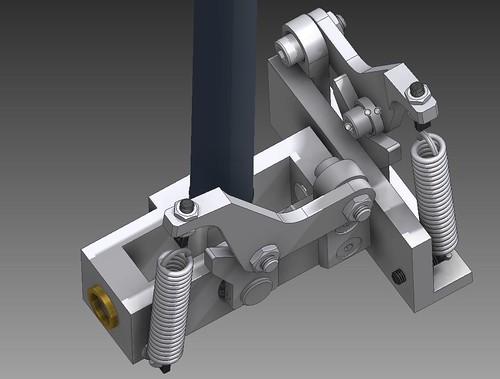
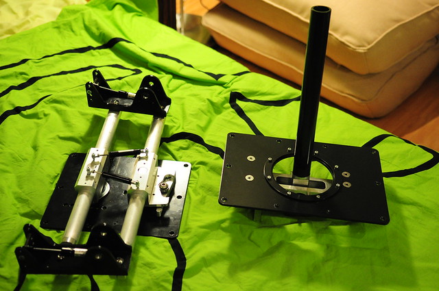
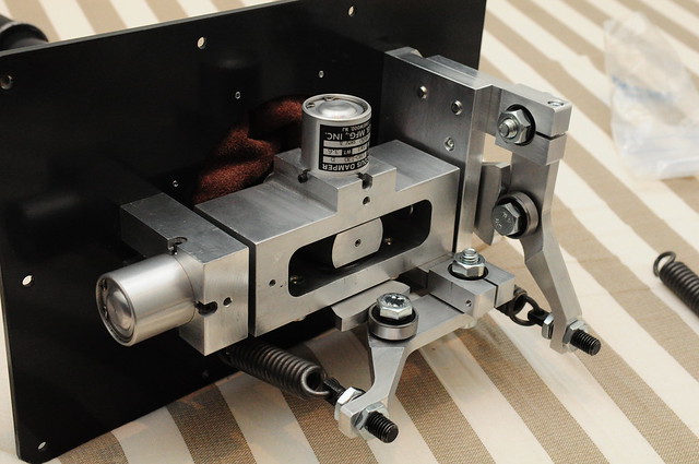
I would like to show the gimbal layout I am currently working on. I use the principle of the real aircrafts "feel and centering unit". Ball bearings are rolling on CAM plates (one for each axis) as the stick is moved. The CAMs forcing the bearing holder arms up and down. These arms lifting the extension springs.
The good thing is, that with different profiled CAMs I can produce different stick characteristics.
I will also use rotational fluid dampers (one for each axis) which will damp the movement of the stick to get a nice smooth realistic feeling.
Wow, very impressive. Are you planning it as a deskmount, or a full-sized floor mounted stick? You've probably got some alternate cam designs already, but I would suggest one with an arc, rather than a V to reduce/eliminate the center detent feel. IJ and his NXT has spoiled me and probably many others in that regard. Looking forward to seeing a prototype.
thx for your input. The gimbal is designed for a full scale control column. As you said, the round CAM shape is very important. The CAM is not V but more like an "U" to eleminate the center detent. The radius at the bottom is quite critical. If it is too big, then the movement can be very floppy around the center. The good thing is that it is easy to make different CAM shapes for experimenting. I don`t know if this design will ever get into manufacturing, at the moment it is more like an experiment. will see..
Baur`s work is truly amazing. He uses the sheet metal very creatively for sure. As I can see his CAM shape is similar to mine, and that is a good sign for me:) I will finish up the design keeping in mind the goal of simple and cheap machining. I still have a long way to go. I have done any calculations neither on the resulting stick forces or on construction strength. I will do this, then I can optimize the design. After all I will ask for some quotations and then I will see the price of dreaming... CNC is never cheap when you make one single piece.
Let me know when you get ready to get some prices. I know several different CNC machine companies around my area of the world that I used to deal with that would love to be able to at least quote the project.
Star Citizen Referal Code STAR-MP6J-VFH7
i7-13700K @ 3.40GHz 32GB RAM GeForce 3060RTX MSI MAG Z790 Tomahawk lots of SSD's and a good old fashioned 1TB HDD Samsung G9 Odyssey 49" TrackIR 5 with Track Clip Pro Windows 11 64bit Warthog #1397...compliments of SimHQ
Currently I am fine tuning the CAM, to have a linear spring extension. Also I am compressing the design to have a more compact size. I am close to the goal, but some more detailed stick force calculation and strength calculation is required.
I have done some more calculation. Due to the long stick, de gear ratio is quite big. It is ca. 1:18 It means that with the usage of 630N springs, the resulting max. stick force will be 35N what is equal to ca 3,5kg. It sounds like a comfortable stick force, however I could live with a bit more, especially on the elevator side. I will have a look on this.
On the strength side I have a lot of reserve, so I can have stronger springs and I can change a few part to aluminium instead of steel.
I tried the stick force on my current cougar setup. It is around 2,4kg and I found it pretty strong in a long dogfight. Therefore I can live with the 3,5 kg. So I am finishing the design and begin the super boring drafting.
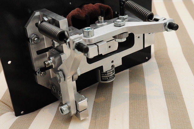
In the meanwhile I wanna show some cool stuff I bought for this project on E-bay. These are high quality industrial rotary viscous dampers. They are damping the rotational movements with the help of silicone oil. They provide +/- 40deg super smooth and !adjustable! damping for both axis. The street price of these gems is 580 USD/piece, so it was a bargain for 20USD each considering that they are brand new. I quickly bought 8 pieces:)
Yep, I think your guess can be quite accurate. I hope the small, family style CNC workshop I have contact with will quote good prices.
The pedal design is coming now. I have some ideas. It is just bloody hard to stand up from the CAD program at work and sit down with the same thing at home:)
Me too. I rather launch a game, than fire up ProE Wildfire or AutoCAD. Although it does make it easier if you have inspiration and want to make something happen. What's your tool of trade?
I have never used ProE, but I haven`t heard about too many happy users either:)
Anyway, I think I found my CNC guy. He turned out to be a flyer as well, we used to fly from the same small airfield, and he is building his own autogiro now. So he is more than happy to help me:) He also offered some cool, aerospace grade 7075 Alu.
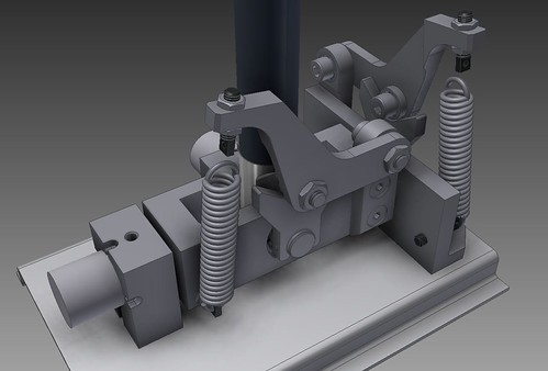
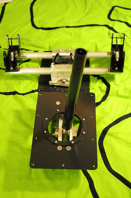
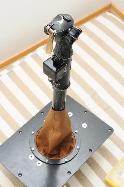
This design is also ready for machining, but before that I had to make some adjustments. I decided to turn the whole gimbal system up side down. So the center of the gimbal can be as close as possible to the mounting plate, while I can use longer springs, and higher mechanism. It is important to keep the center close to the plate, otherwise I can end up with a huuuuge opening on it:) I installed longer springs, so I can have some more pretension on them. Just like on the pedals I decided to use a simple steel mounting plate. The opening will be covered with leather boot.
I saw in one pic you have a square movement limiter, but in the later pics they are round (unless the gimbal does the limiting) Make sure you have a square limit of movement!
I saw in one pic you have a square movement limiter, but in the later pics they are round (unless the gimbal does the limiting) Make sure you have a square limit of movement!
cheers Julian:)
The limiting is done within the gimbal. The CAM plate movement is limited by two screw heads. The round cut out is pure cosmetic, the stick won`t contact with it and will have square boundaries.
ir seems a promising product are you going to sell them by any chance?
Last edited by Bluedeath; 05/14/1202:23 PM.
"When you plan revenge best dig two graves" Confucius "They who can give up essential liberty to obtain a little temporary safety, deserve neither liberty nor safety" Benjamin Franklin
ir seems a promising product are you going to sell them by any chance?
Thx chaps for your credit. If this prototype proves itself "airworthy" and reliable through a good amount of testing, then it will be possible to make a short run of it. I will keep you updated.
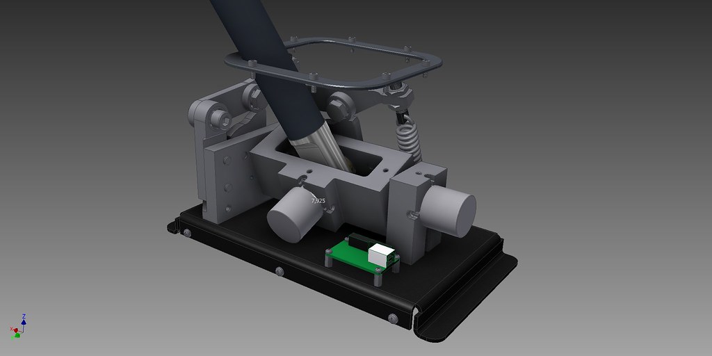
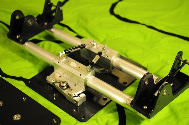
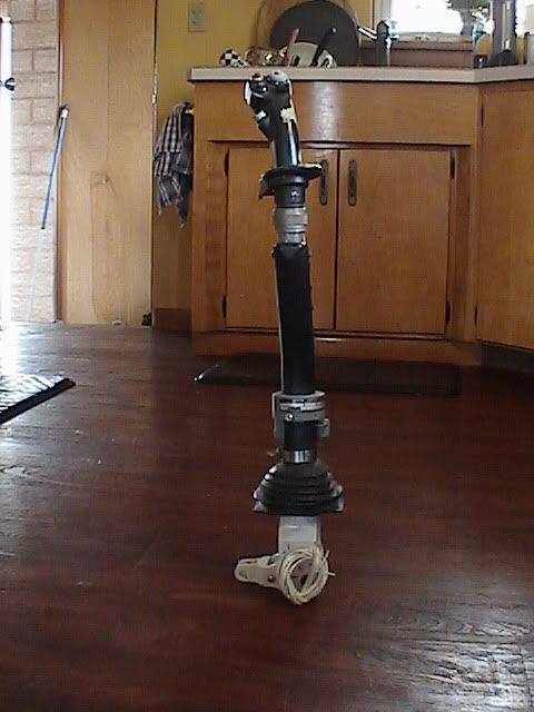
just a quick work in progress update shot. All parts are finished, assembling is on the way. Steel parts are powder coated to RLM66 grey. It is all coming together really nicely:) Further update will follow soon.
"When you plan revenge best dig two graves" Confucius "They who can give up essential liberty to obtain a little temporary safety, deserve neither liberty nor safety" Benjamin Franklin
That looks well engineered I am very eager to see your testing regarding quality and longivity and if you decide to sell it, I might be a buyer if it's not too expensive (I know it will be expensive just now much is the question)
Looks very interesting. are you going to manufacturing it yourself or make a workshop do it. If so os it possible to join in and order 1 such piece please
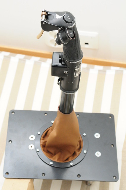
OK, here is some progress. I fully assembled the mechanism of the gimbal. It is basically finished, but I need to shorten some spring consoles. The column got its leather boot in beautifull Porsche Cayenne internal colour:) And finally I monted its crown jewell, the KG13 grip:)
The mechanism works perfectly as far as I could test it. Probably I will make a new CAM profile to create a more progressive control load character and to have a soft, mushy center feeling. The current one is just too noticable for my taste.
you need 3 wires for each pot like is explained on Leo's site image and since you just need 4 buttons you can connetc the button matrix pins to ground (with the switch in the middle of course)
"When you plan revenge best dig two graves" Confucius "They who can give up essential liberty to obtain a little temporary safety, deserve neither liberty nor safety" Benjamin Franklin
unfortunately I am not quite sure which are the matrix pins, and what switch is supposed to be in the middle. As I mentioned I am really dumb to electronics:)
if you can cannibalize pots from joystick regular pots have 270� of travel while you need 45~90� ones (best would be to use hall sensors)
"When you plan revenge best dig two graves" Confucius "They who can give up essential liberty to obtain a little temporary safety, deserve neither liberty nor safety" Benjamin Franklin
can you put me in contact with the guy? Pay a lot of attention on the polarity (don't switch by mistake +5 and GND).
"When you plan revenge best dig two graves" Confucius "They who can give up essential liberty to obtain a little temporary safety, deserve neither liberty nor safety" Benjamin Franklin
Thanks that's the last par i needed to start my world domination plan mhuahahah!(devilish laugh). I owe you one you just made my wife very angry with me (but she will never discover that I'm still working on my cockpit)
Last edited by Bluedeath; 07/19/1211:19 AM.
"When you plan revenge best dig two graves" Confucius "They who can give up essential liberty to obtain a little temporary safety, deserve neither liberty nor safety" Benjamin Franklin
I share the study room with my wife a good pair of headphones is as much as privacy i can get.
"When you plan revenge best dig two graves" Confucius "They who can give up essential liberty to obtain a little temporary safety, deserve neither liberty nor safety" Benjamin Franklin
If i may suggest a very minor change, turn the leather boot inside-out and fit it upside-down on the control column, fix it with a zip tie and then turn it back outside-in before fixing it to the base. That way it will look a little more polished and keep a little more dust out.
If i may suggest a very minor change, turn the leather boot inside-out and fit it upside-down on the control column, fix it with a zip tie and then turn it back outside-in before fixing it to the base. That way it will look a little more polished and keep a little more dust out.
Thank you for the tip Brandano, i will give it a try when the wiring is settled.
Well, I could not resist and quickly installed the sensors and took the stick for a quick spin within CloD. Well the stick was laying on my knees, so it was far from optimal, but maaan it is sweet!:) With the long stick, the precision sensors and the smooth hydraulic damping it feels awsome. I can`t wait to be finnished and test it properly.
The difference between You and me is that you're clearly not stupid when it comes to engineering! I could never build a piece like you've put together.
My time is better spent working overtime so I can buy one when they go into production
BTW; when does the force Feedback version come out?
My Rig:i5-3570k @ 4.2 GHZ W/ Corsair Hydro H110 Cooler / Asus Sabertooth Z77 Mobo / GTX 1070/ 16 Gigs DDR3 RAM / A Few SSDs, and a Bunch of HDDs / All held together by: Corsair C70 Case
Other Assets Deployed: HOTAS: Thrustmaster Warthog SN#22621/CH Throttle Quad/MFG Crosswind Pedals SN#0004 TrackIR TIR 5 w/ TrackClip Pro Simpit: Obutto R3VOLUTION
BTW; when does the force Feedback version come out?
Thanks man:)
I have given a lots of thoughts to a possible FFB design. From mechanical side, it would be quite an easy job. The bigger challange is hiding in the electrical design. I should find an expert who would cooperate to put a design together.
If i remember correctly Leo Bodnar (don't kill me if is not him) done some experiment the real problem in the end turned out to be the software programming ,and the fact that is not possible to send different FFB signals in windows but all the peripherials will receive all the signals (or something like that)
"When you plan revenge best dig two graves" Confucius "They who can give up essential liberty to obtain a little temporary safety, deserve neither liberty nor safety" Benjamin Franklin
Well I am only using common sense, but is there any problem with using an existing controller+driver from an ffb joystick (MS ffb2) and attach stronger motors to it? Theorically some signal amplification could do the job. Mechanically only a right gearing is needed to put out the right deflection to the stick.
Anyway it is all just thinking for me. I don`t plan to start a new build in the near future. I will be glad enough if I can finally finish this one
Well I am only using common sense, but is there any problem with using an existing controller+driver from an ffb joystick (MS ffb2) and attach stronger motors to it? Theorically some signal amplification could do the job. Mechanically only a right gearing is needed to put out the right deflection to the stick.
Yeah, that should work (in theory ). Played with the same scenario in my mind, but with the original Wingman Force.
The nice thing about the FFB signal reaching all controllers; for a P-38 yoke I could attach the X -axis motor from the Wingman to the Y-axis output (reversed) for a kind of push-pull setup on the Y-axis (ignoring the X-axis). The wheel of a Wingman Racing Force (converted to yoke) will handle the Y-axis.
In your situation, you could have two Sidewinders, reversing polarity on one of the sticks' motors and create a push-pull configuration on both axes. Double the forces.
as I described in the Pedal`s thread, the testing is delayed due to the lack of space and testbed, but it will change soon. Meanwhile I got my new reshaped CAM profiles for the stick.
Now I am pretty happy. I have 0 center feeling. On the first few inches there is only the damper`s resistance, and a very slight centering force. Literally the stick stays where I leave it. Then the centering forces build up exponentially, supplemented by a very smooth and strong damping. Maybe I will try a bit weaker spring on the aileron side. All in all it is pretty close to what I am used to in a real aircraft.
I was planning to make such a choice. Put their profile. And ... refused. The profile should be asymmetric. After the pedal you should know this. In various aspects of the movement stick is different in kg. I hope you were able to calculate the effort?
I apologize for my English.
I'm angry that did not give me a link earlier in this wonderful job ....
Privet Baur!
It is good to see you, a great designer at this forum! I made asymmetric CAM profiles for the gimbal as well. I used some geometric calculation to achieve similar forces in both directions. They are not 100% accurate, but they are quite close to it.
It is good to see you, a great designer at this forum!
I'm a simple guy like you. Aviation - our disease ...
Originally Posted By: VO101MMaister
I made asymmetric CAM profiles for the gimbal as well. I used some geometric calculation to achieve similar forces in both directions. They are not 100% accurate, but they are quite close to it.
That is good. I was asked about it. The problem is that the hand feels better. Feet on the pedals so you can not exactly count It was very difficult to make such a calculation!
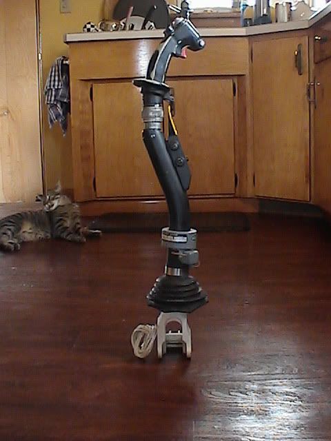
That is quite a piece of art you have there. Is it from an A10? By the way, it shouldn`t be a problem to use it with the gimbal, although the joints on the bottom (the white parts) would have to be removed.
HI yes the stick is out of an A-10A and the grip out of an F-16C so it is the same as in an A-10C The whit half of the joint could be remove after establishing the correct pivot point with your system
I've seen the Boeing 737 cam design, but dismissed it as too complex for my use... never occurred to me to sit over it and simplify. Thank you VO101MMaister for inspiration, will try to work on it to get it fit into Cougar stick base with force trim unit. Hey if it's not hard, it's not worth doing, right ?
Sounds like a nice engineering challenge to squeeze it into that small housing! Good luck and keep us posted about your work!
About my project.
Currently I am tackling with a much bigger project in my free time (house renovation) so this one (and sims generally) is put aside for a while. The good thing is that afterwards I will have a dedicated place for my gear:) I will keep you updated when there is any progress!!!
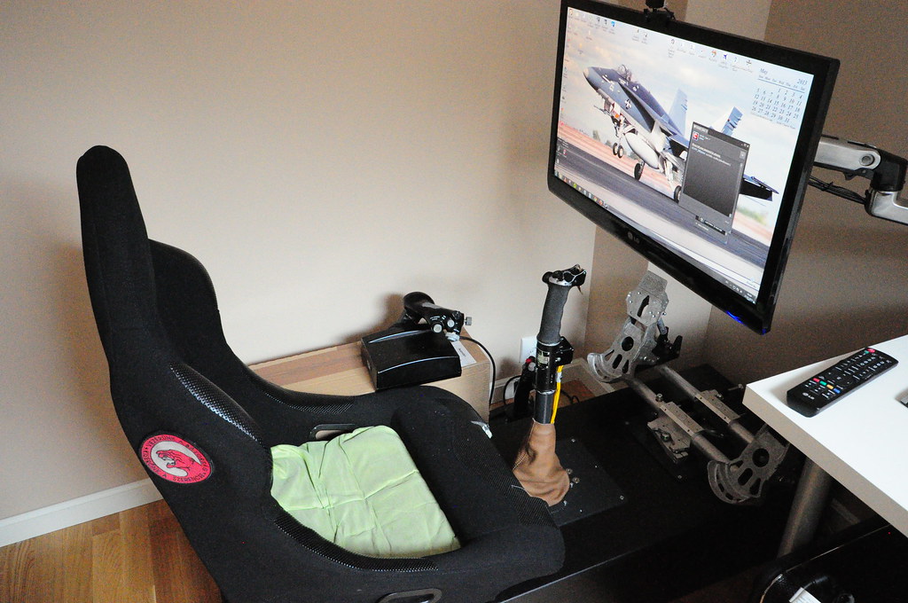
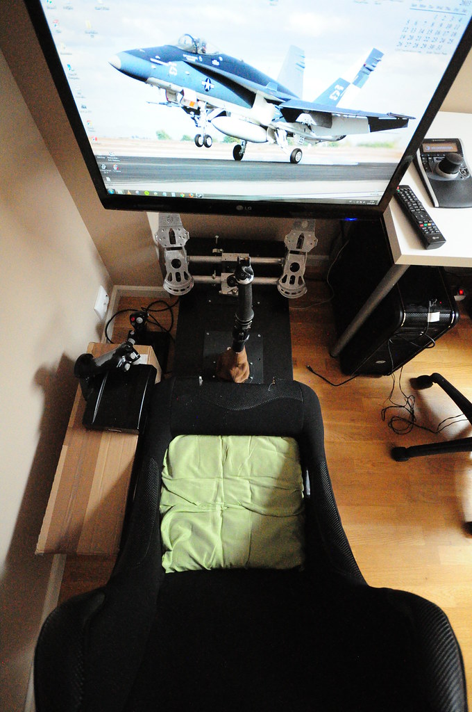
finally everything is in place. I have used the system for a few hours and I am very happy:) It feels really solid and super accurate. Later I will make a small platform for the throttle, and keyboard.
wow.. amazing work!!!!! i hope to show off my finished product come january.
i think i have 2-3 weeks till i finish my cyclics, then i will proceed to build torque pedals..
by the way, im not sure if your devices are stand along.. AVOID having all the units (pedal, joystick throttle/collective) stuck together in one platform...
my previous build was a platform. it sucked taking it apart. i am making my setup modular... including the seat where if i didnt have no controllers connected, i can still enjoy sitting in the chair by itself..
your stick.. looks effin amazing. only con i have about your set up, is that your stick is way to far from the chair.. 3-4+ hours of flying, your arm will get tired from extension. (i could be wrong in which you have referenced actual cockpit designs)
in my helicopter setup, im trying to put my joystick a few inches from my crotch...
alright. in my setup, my joystick would be next to my crotch in pulled back position, in my thigh before my knees when centered, and between my knees when the joystick is full forward.. (im setting my stick to have a 6" +/- deflection)
alright. in my setup, my joystick would be next to my crotch in pulled back position, in my thigh before my knees when centered, and between my knees when the joystick is full forward.. (im setting my stick to have a 6" +/- deflection)
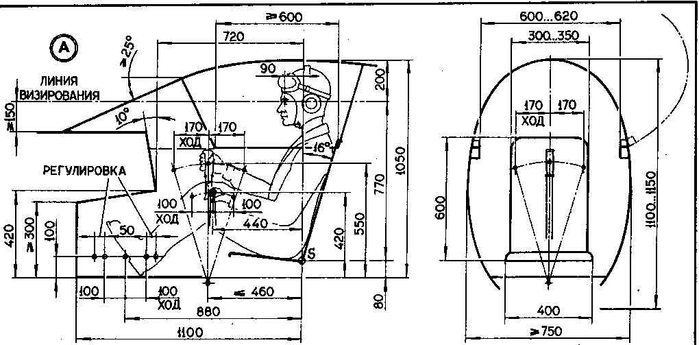
I think that is pretty confy setup, and very similar to the modern helicopter and sport aircraft layouts. I am flying motor gliders and the stick is placed pretty much where you described.
My control stick is placed a bit further forward because of the limitation of the seat I use. I could use a bent column of course, but the current config is quite ok. It is also very similar to the common ww2 era warbird layout.
i saw that photo in the eagle dynamics / DCS forums a few months ago, but was unable to find it again. my search came up with fa-18 seat dimensions
it didnt help me much, im pretty much going by trial and error to see what height and seat angle to make my seat base. i hope to start my seats in 2-3 weeks!
I know it has been several years since this thread has been touched but what can I say, I'm really impressed.
VO101MMaister, if this design isn't going to go into production would you consider open sourcing your design? I'm currently investigating the possibility of building a sim-pit for a glider and am looking for a way to make my own control column and what can I say, this design looks FREAKING AWESOME!!!


![[Linked Image]](http://www.simhq.com/wp-content/uploads/2013/06/SimHQ1.png)