by Andy Bush
Introduction
In the previous discussion of flight simulation views, I evaluated each type of viewing system with regard to how effectively each system allowed you to see the need for and then perform basic BFM maneuvers. This comparison placed its primary emphasis on the amount oftime that each type of view required to determine and implement the BFM maneuver. My conclusion was that the external view, specifically the player-to-target view, gave the pilot the best opportunity to reach his twin objectives of correct maneuver choice and timely maneuver performance. I concluded that it was the “outside the cockpit” perspective of the external view which allowed the pilot to see both aircraft at one time in a 3D spatial relationship. I noted that this perspective gave us the best intuitive sense of the particular BFM problem at hand. At this point let’s stop for a moment and recognize that this intuitive grasp of BFM is not inherent in the pilot…instead, this insight starts in the mastery of specific BFM concepts and is perfected through practice. In this article I will continue this line of thought by discussing a number of those concepts, all of which can be thought of as building blocks in the development of that intuitive feel for BFM.
Discussion
The building blocks of intuitive BFM can be grouped into two areas:
1. General Aerodynamic Principles
2. General Offensive and Defensive Maneuvers
I’ll begin with a discussion of the first building block, general aerodynamic principles, and in a subsequent article I will discuss various BFM maneuvers which you may use to gain an advantage over your opponent. But first, I need to make a disclaimer! This article is about flight simulation BFM. It is not necessarily a primer for real life BFM because there are some very significant limitations in how well air combat simulations replicate the real world…and, not only do these simulations share collective limitations, but individually they vary widely in the accuracy of their flight models. Therefore, this discussion will center on concepts and principles that you can use in your simulation. How well your simulation takes advantage of these concepts is difficult to quantify, but one thing is certain. These concepts are timeless…they are the “prima franca” of air combat maneuvering techniques. They may or may not be as effective in a simulation as in real life, but they will, as a whole, give you the basic foundation so necessary for the “big picture”, the intuitive feel for the right maneuver at the right time.
General Aerodynamic Principles
1. The Effect of Gravity. Gravity, or “God’s g” as it is sometimes called, can be a big player in overall BFM maneuver effectiveness. As we all understand, gravity is always with us…pulling us “downwards” towards the earth. We counter that force with one of our own which we call lift…but, when in level flight, we must remember that the lift force or “vector”, is always being opposed by gravity…thus, the magnitude of our lift vector is always effected by gravity. In the cockpit, we read our lift vector g on the g meter, either positive or negative. We sometimes forget, however, that the g force which affects the actual performance of the aircraft is the end result of God’s g (gravity) and our cockpit g being mathematically combined to produce a resultant g force known as “Radial G”. When we think of maximum performance in our maneuvers, we mean max turn rate and min turn radius. These two turn parameters are affected by your Radial Gand your true airspeed. The effect of God’s g is easily seen. Keeping in mind that turn rate and radius are improved as Radial G is increased, when your lift vector is pointed below the horizon, God’s g adds to your cockpit g and therefore improves your turn performance. The g you are seeing on your g meter is actually less than the total g which is affecting your aircraft. Now, orient your lift vector above the horizon, and the opposite is true…you get less turn performance since Radial G is less than what you see on the g meter. The difference is most pronounced when your lift vector is perfectly vertical to the horizon. The following two diagrams explain the Radial G concept.
Imagine you are pulling 4 cockpit g’s…when you are wings level and upright, God’s g  subtracts one g from your resultant lift vector…you end up with a resultant force (Radial G) of 3 g’s.
Now if you roll wings level inverted, God’s g adds one g to your cockpit g, bringing your resultant Radial G up to 5.
The end result is that in our example the inverted aircraft is performing about 50% better than the upright aircraft for a given airspeed. Now, these performance differences decrease once the aircraft leaves wings level flight, but the important thing for you to remember is that lift vector  orientation can significantly affect your turn performance. One final point on this subject needs to be made. In the above figures, we show both the lift vector and the Radial G resultant vector. The significance of this diagram is that you understand that the lift vector isnot the direction your aircraft is going…instead, your actual flight path is the Radial G resultant vector. In aerodynamics, this Radial G vector is called the acceleration vector. In this sense, acceleration does not mean speed up or slow down, instead it refers to the Radial G force direction. As an aircraft moves through the sky, it is being affected by Radial G and the force of its own velocity. These two forces can be thought of as flight path vectors linked together at the aircraft, and, together, they form the plane of motion. I’m sure you are wondering what is the point of all this “rocket science”…simply put, it is to introduce this concept of the plane of motion. As you maneuver against your opponent, it is your ultimate objective to get yourself into his plane of motion…in doing so, you will have solved the BFM problem of controlling closure and aligning fuselages. So, let’s talk for a bit about what this plane of motion is, how you recognize it, and how the external view gives you the best look at it.
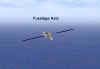
2. The Plane of Motion. Whew, I can hear you say!! Finally, something you have heard of…the plane of motion. Just so that everyone understands…the word “plane” doesn’t mean “airplane”…no, we’re talking about “plane” in the sense of a “flat plane of glass”, for example. This “plane” represents the flight path of our aircraft. Please note that the plane of motion is  aligned with the rudder, not the wings.
Now, if another aircraft comes along whose velocity vector and radial g vector are oriented in a different direction from our aircraft, then its “plane of motion” will intersect ours and form a three dimensional figure looking something like this:
Since these two planes are not in alignment, we refer to these two planes as being “split“. And so, the two aircraft who are maneuvering within their separate planes of motion are  engaging in split-plane maneuvering. They are maneuvering out of plane with regard to each other. Pilots will maneuver out of plane to gain an advantage. They do this to gain additional turning room and to use the beneficial effects of God’s g. This allows them to control closure, aspect, and angle off. In the last issue’s article, I defined BFM as the “control of closure, aspect, and angle off”, and I said split-plane maneuvering was “efficient BFM”. Therefore, when we look at Figure 4, we see a diagram of two aircraft maneuvering against each other, presumably to gain an advantage against the other. Now look at Figure 4 again, remove the planes of motion, and imagine it as the player-to-target view.

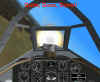
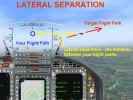
Aha!! Now we are getting somewhere! In this screen shot, we see the attacker bringing his nose up and out of the plane of turn of the defender. This is how the beginning of a High Yo-Yo looks from an external view. Remember, this is an article about using the external view in BFM. If we fly our simulation using an external view, then the obvious question becomes one of how we orient our lift and velocity vectors to establish a plane of motion for ourselves that gives us an advantage over our opponent. When we use the external view, which way do we roll and/or pull to achieve that advantageous split plane? That is what the remainder of this article is going to talk about…how we solve the problems of controlling closure and achieving required turning room.
3. Using the Flight Path Vector To Control Closure. In addition to using the throttle to change your speed relative to another aircraft, you may vary your closure by changing your nose position. In doing so, you are changing the direction of your velocity vector…you are giving your airspeed a new direction. Depending on the relative position between you and your opponent, this new velocity vector direction will result in a increase or decrease in closure, often without any corresponding change in your indicated airspeed. This happens because your new flight path covers either a longer or shorter distance resulting in a longer or shorter length of time. When you attempt to re-direct your flight path vector with the external view, two things are immediately visible on your monitor…the size of the change in your flight path – how you have changed your angle off – and the effect of that change on your position relative to your opponent – how this maneuver has changed your closure. At this point, let’s get a mental picture of what we have just done…we have positioned our flight path away from the opponent, thus gaining some separation, and we have made a correction in our rate of closure. We are now in position to complete our pursuit of the opponent…all we need is enough turning room.
4. Required Turning Room versus Available Turning Room. When attempting to bring your weapons to bear on your opponent or when attempting to align fuselages, one parameter is always a major consideration…do you have the room necessary to complete the turn? Too often we may find that the turning room which we have to work with is just not sufficient for us to put our lift vector on the opponent and pull…what will result if we try this is a flight path overshoot which may well offer our opponent the chance to reverse roles and become the attacker. The issue here is being able to visualize the field of maneuver as being more than two dimensional. Someone once said the shortest distance between two points is a straight line…who ever that guy was never flew BFM!! In the following figure, the F-15 cannot simply roll, put his lift vector on the target, and then pull…he will overshoot since his turn radius is larger than the available turning room.

Therefore the question becomes “where does the pilot find additional turning room” in situations like this? By now, I think you know where I am headed…the pilot must reorient his flight path vector out of the plane of motion of the opponent. “Well, that’s fine”, you say, “but how do I do that?” Excellent question. You do that with your aileron…you point your lift vector and thus your flight path vector by rolling your aircraft to a new bank attitude relative to your opponent. You get out of plane with aileron…how far you get out of plane is determined by how long and how hard you pull back on the stick. Of these two control inputs, roll is more important than pull. Your first problem is to get out of plane…having done that, then you can worry about how much of a change to make.
One very important principle must be understood…the relationship of the opponent’s plane of motion to the horizon is not of immediate significance. Regardless of the opponent’s plane of motion, when additional turning room is needed, you should roll to point your lift vector away from his plane of motion…as much as 90 degrees if necessary. The external view makes this repositioning maneuver easy to visualize. The amount that you get out of plane with your opponent and the amount of separation needed is a direct function of how much additional turning room you need. For example, if you see a major flight path overshoot coming up, you need to aggressively break out of the opponent’s plane of motion and maintain your new flight path until you can safely pull back towards the opponent. Please note that I did not use the words “pull back down” or “pull back up” in reference to your re-entry to the fight. This is because there is no “up” or “down”, i.e., no reference to the horizon…the primary consideration is to get out of plane.
5. “Hedging My Bets” or Required Turning Room versus Available Turning Room, Part 2. Now, having said that, let me cover my tracks by saying that, as always, nothing is ever quite “black or white”, no case is ever “open and shut” in BFM. There are, once again, additional considerations in making your bid for more turning room, but, for the level of our discussion, I believe they are less significant…not to be ignored completely, but definitely not front burner material. Of these, two merit some discussion…your energy state at the initiation of the out of plane maneuver, and the effect of God’s g on your maneuver. Both of these factors essentially bring the same thing into the equation…the location of the horizon relative to the opponent’s plane of motion.
As we have mentioned earlier, your airspeed (in this case, true airspeed) is one of the two determinants of turn radius and rate. We also discussed the difference between the terms of airspeed and closure. You read your airspeed off the HUD, but your closure, for a given airspeed, is a function of angle off. The following figures makes this clear:
In Fig.7, with the opponent at a 90 degree crossing angle, the attacker’s closure is his true airspeed since the opponent’s velocity vector neither adds to or subtracts from the attacker’s velocity.
However, in Fig-8, the opponent is moving away from the attacker at an angle. If we were to break the opponent’s velocity vector down into components relative to the attacker, we would find that a portion of the opponent’s velocity vector is aligned with the attacker’s velocity vector and. as a result, reduces the attacker’s closure. In both cases, the attacker has the same indicated airspeed, but his closure differs significantly, and, therefore, the magnitude of his BFM maneuver required to control this closure is also different. What this means to you as the attacker is that in the first case, you may well have to make a throttle reduction and a major flight path change to control your overtake, whereas, in the second case, you may well be able to manage your closure with either a throttle reduction or a small yo-yo. My point to you is that your indicated airspeed is not a very good measure of the BFM closure problem. Your total energy state is actually a combination of your indicated velocity (airspeed) as well as your relative velocity which arises from the geometry of the set up.
A second factor which you need to also consider is the positive or negative factor that God’s G may bring to your attempt to gain turning room. We have already explained how radial g (along with true airspeed) is the determining factor in your turning performance. You, as the pilot seeking the greatest advantage in your choice of maneuvers, want to take full use of the positive aspects of God’s g while minimizing the negative. How you do this will be covered in the second part of this article…for now, it is important that you understand that radial g is a variable which you control, just as in the first example, both throttle management and flight path direction (velocity vector control) are variables which you directly affect. The bottom line is that recognizing and achieving required turning room is the dominant problem in offensive BFM.
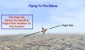
6. How To Recognize Relative Energy States. Now we are getting down to the nitty-gritty…I see the opponent…I need some smash…where do I get it from? Well, you could always take the brute force approach and throw it into burner. But what if you don’t have that option…such as you are already in afterburner, or you are close to bingo and cannot afford the extra fuel consumption…is there another way? There well may be if you can take advantage of any energy potential which exists because of your relative position to the opponent. If you are above his flight path relative to the horizon, you have some potential energy due to your altitude advantage which you could use…just lower your nose slightly and let God’s G help you out. An easy remedy to a closure problem…but I want to offer something a little more subtle. I want to introduce what I think of as “the high wing/low wing” view of energy management. In a way I’m just restating the ideas already put forward about God’s G, but, while theory is fine for textbooks…how about a technique you can use in the cockpit? Here it is…hope you have luck with it.
In the diagram, the aircraft is viewed relative to the horizon. What we want to do is to identify the target’s plane of motion. You do this by using the target’s rudder as an approximation along with the extension of the target’s fuselage axis. These two lines define the plane of motion. Now we compare this plane of motion to the horizon. In Figure 10, the aircraft is oriented in a right bank and is upright to the horizon with its plane of motion canted approximately 45 degrees from the vertical. If you climb above the target’s plane of motion, you are exchanging kinetic energy for potential…in other words you are slowing down. If you fly to the area below the target’s plane of motion, you are doing the opposite…exchanging potential for kinetic…you are gaining speed. As you view the target’s plane of motion, it is easy to relate that plane to the horizon. Do this and you then may see the target’s wings as being oriented above or below the horizon. As you view that aircraft, I want you to think of his low wing as pointing to the positive or energy gain area, and his high wing as pointing to the area of negative or reduction of energy area.

The concept is simple…want to pick up some smash or at least not lose any…then fly to his low wing. Need to bleed some smash…control your closure…then “raise” your nose a little and point yourself towards his high wing. Think low wing equals acceleration, high wing equals deceleration…piece of cake!!
7. The High Six and Flying To the Elbow. This last area in this discussion ties it all together. We’ve talked about using God’s g, planes of motion, control of our velocity vector, turning room, and relative energy states…now let’s finish by presenting a view of where we want to be to blow our opponent away. We want to be behind him with our closure under control…we want to be in a position of command. You may have heard of this concept before…it is not original with me, but I endorse it highly…it’s called the High Six O’clock. Of course, this is your opponent’s six which we are talking about! We get there by orienting our flight path vector and managing our closure to arrive at that point in the sky known as the “high six”. The word “high” in this context means relative to the horizon, not to your opponent. His attitude..upright, inverted, whatever..is not a consideration. You want to maneuver to a position which is behind your opponent and “above” him relative to the horizon. Why and how far behind? This is strictly a function of your choice of weapon…for a gun attack, I like to stay in close…definitely inside 3000 feet. Why “above”? The answer is one I’m sure you now know…because by flying to that position, we control our closure to make sure our opponent stays out in front. One way to visualize this concept is to use our forearm as a reference.
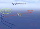
Our hand will represent the opponent, and our elbow will represent the “high six”. Like all fighter pilots, we use our hands to illustrate a maneuver. You are your free hand…no matter what position you place your other forearm in, you want to maneuver your free hand back around to your other elbow. This is a “must” for you to understand…you maneuver to the elbow, not to the opponent! No matter which way your opponent is heading, no matter which way the horizon is…you fly to the elbow. Your turning room requirements, your energy needs are predicated on getting to the elbow. Wow, I can’t say it stronger than that!!
Summary
I want to conclude by reminding everyone that we are talking about using external views to learn air combat simulation BFM. My opinion is that the external view allows you to “see” from an “out of cockpit” perspective the three dimensional BFM problem. The “high six” and the “elbow” are more easily perceived using the external view than in any other view. Try it, and with practice, I think you will appreciate it’s effectiveness…see you next time.
Related posts:
 Air Combat Basics: The Scissors Maneuver
 Page 2
Air Combat Basics: The Scissors Maneuver Page 3
Air Combat Basics: The Scissors Maneuver
Air Combat Basics: The Scissors Maneuver Page 2
Air Combat Basics: The Scissors Maneuver Page 3
 An Introduction to Simulation BFM, Part Two
 It’s All a Matter of Perspective – Part Four
 It’s All a Matter of Perspective – Part Three
 It’s All a Matter of Your Perspective – Part One
 The Falcon 3.0 Manual Tactics Section – Introduction to the Geometry of Air Combat